Ape hosts and Ape handles

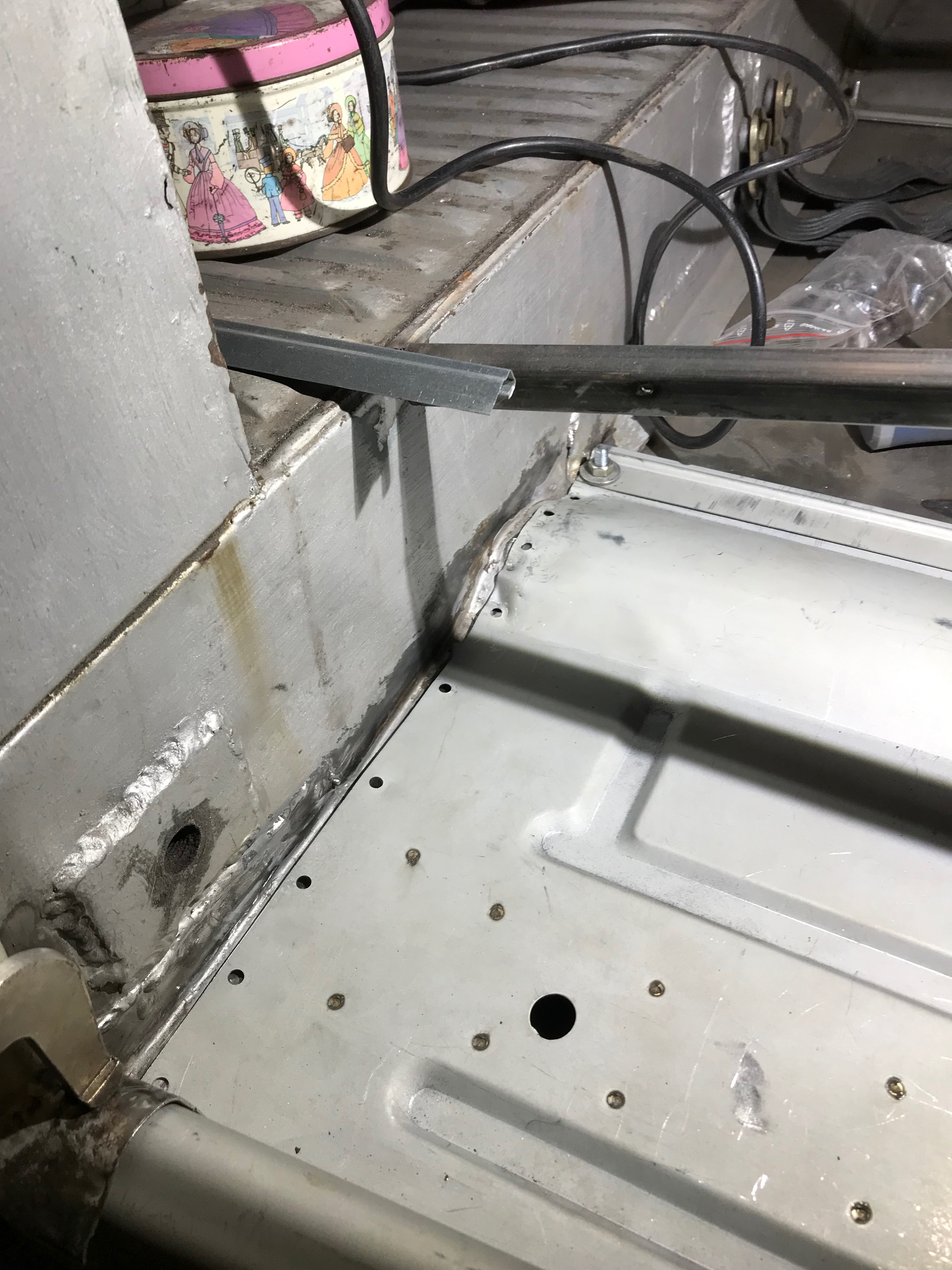
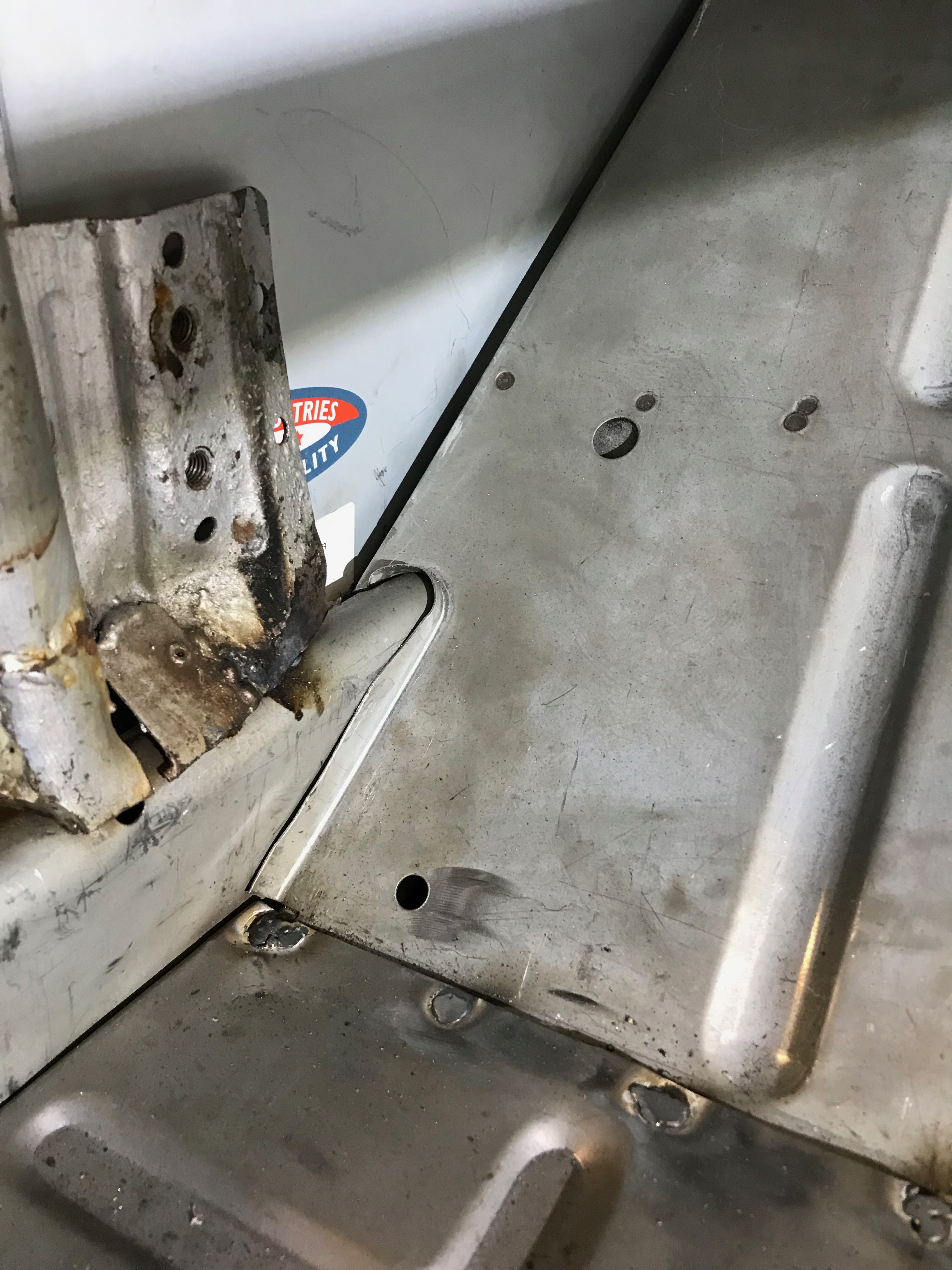
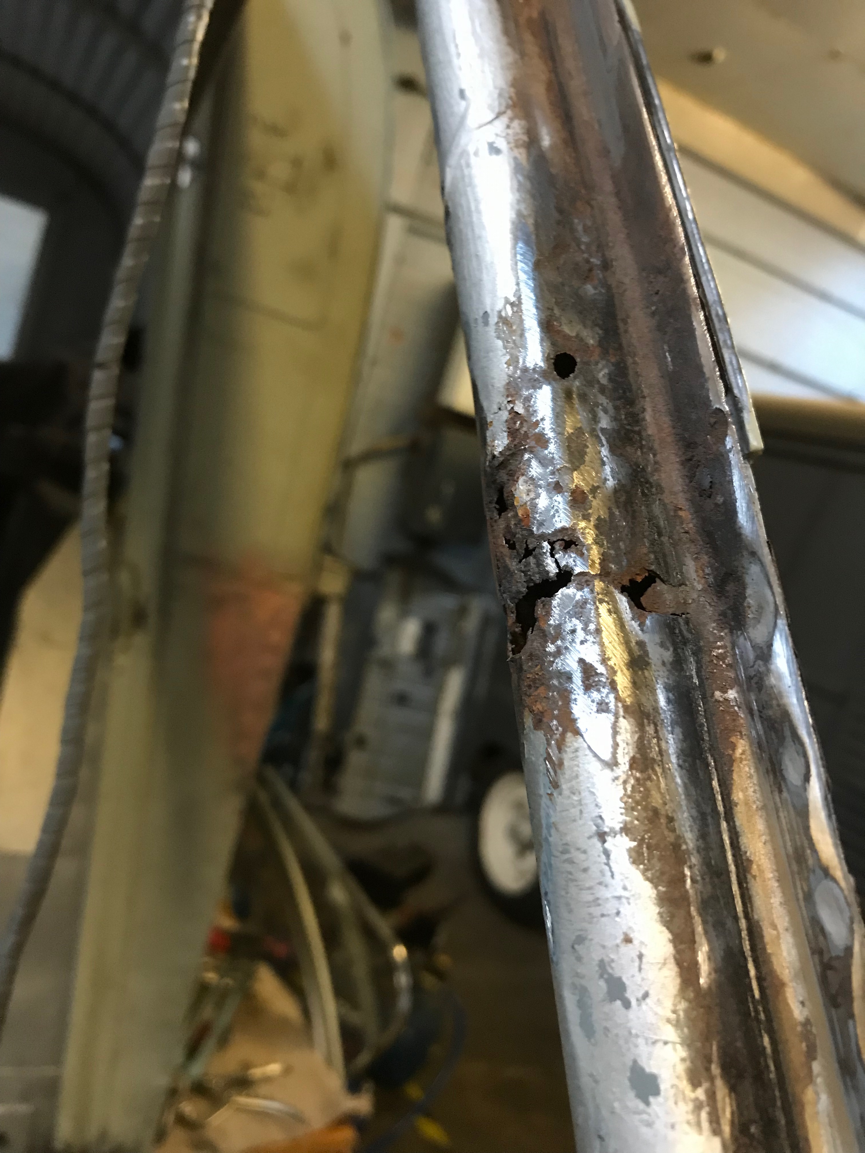
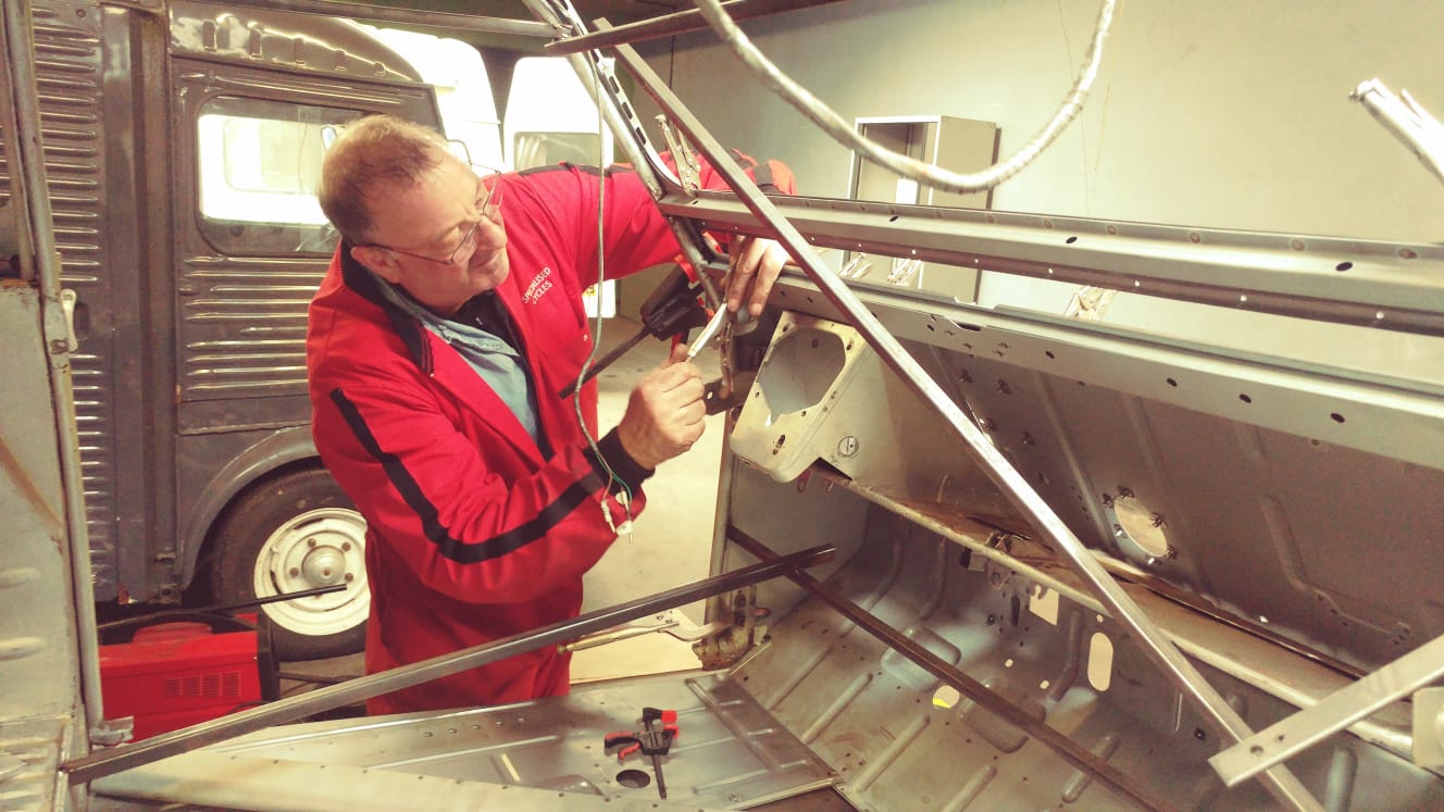
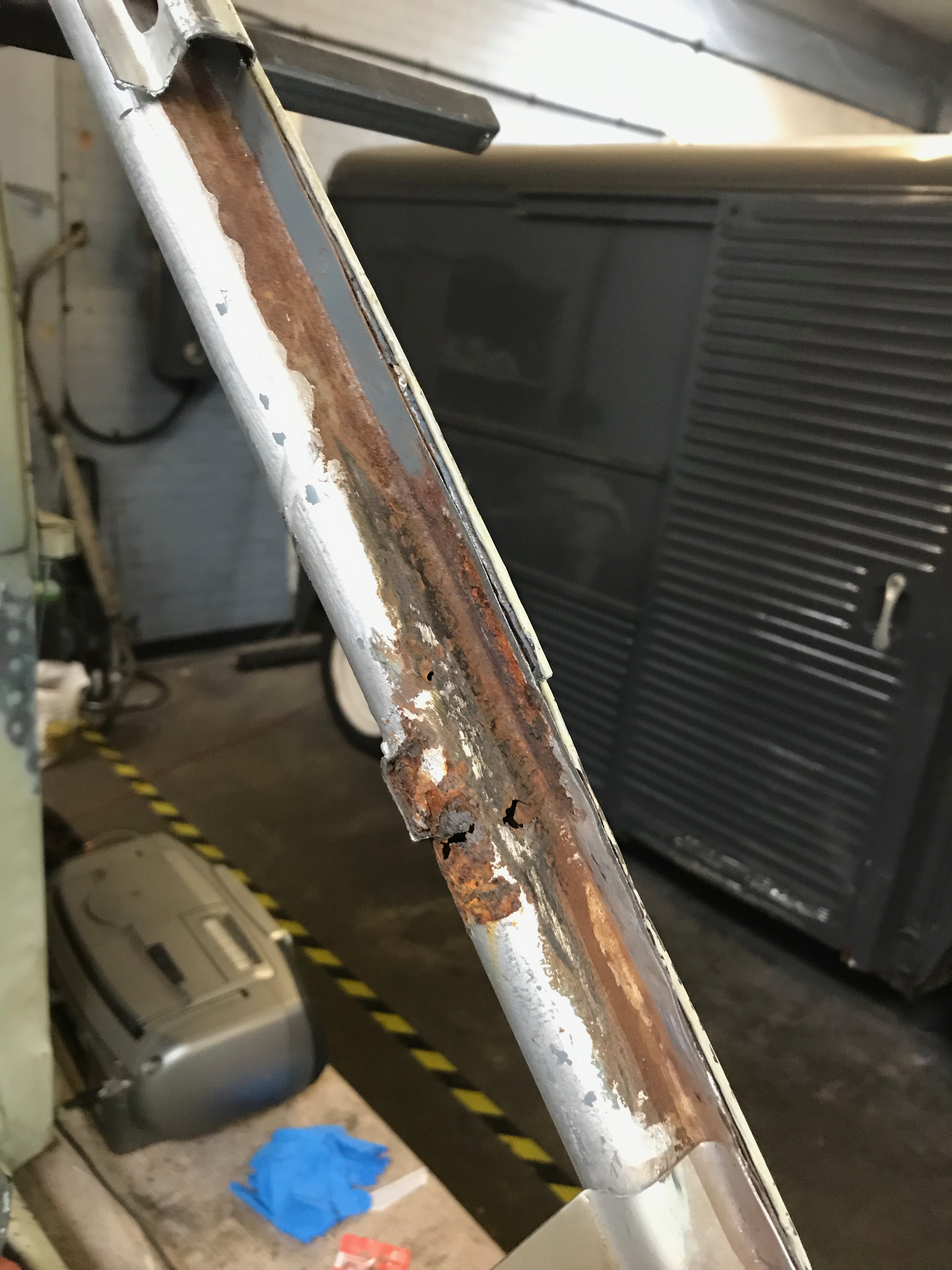
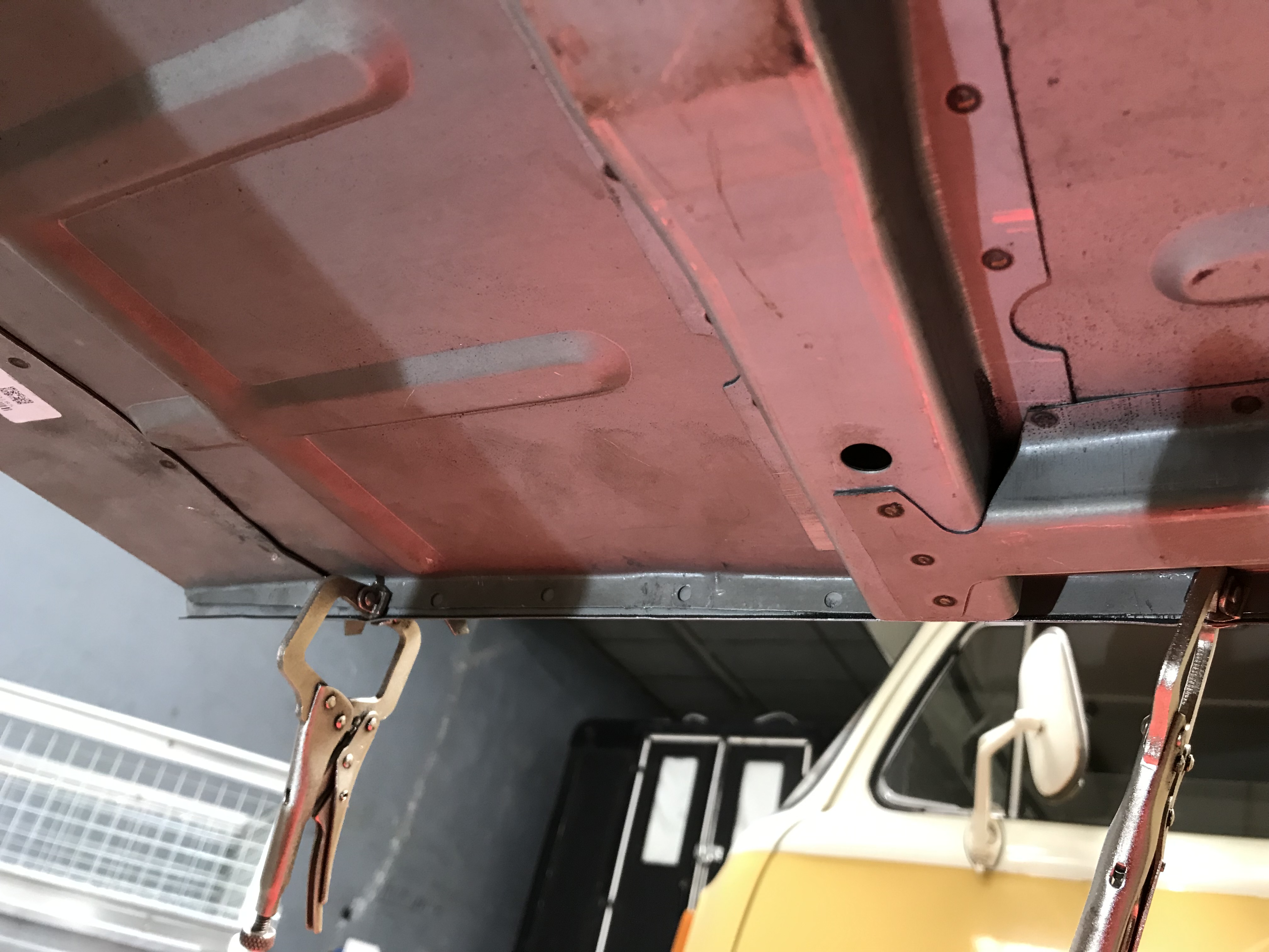
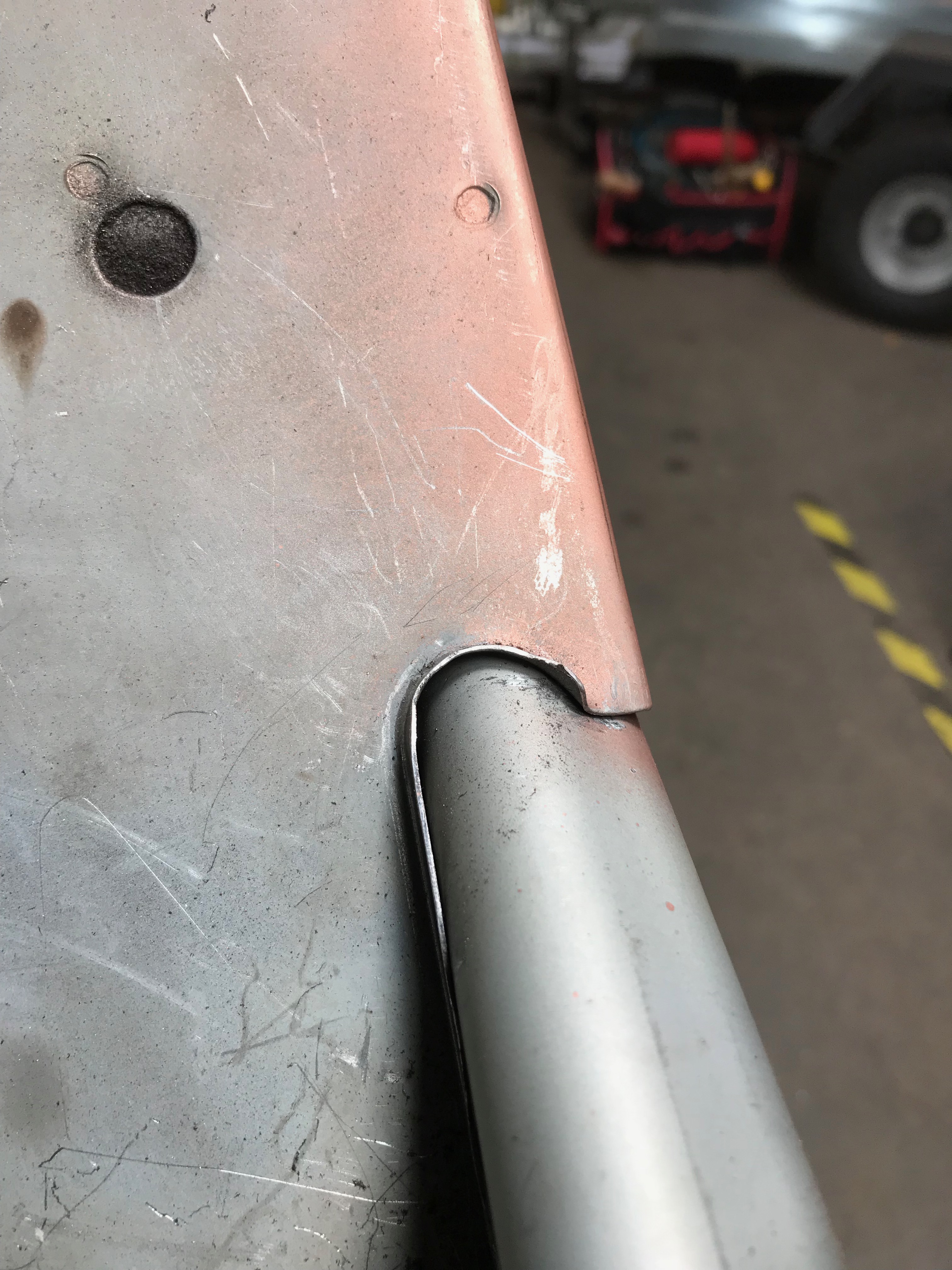
Time to tackle the botton of the A posts where they meet the sills. It’s all pretty grotty down at there on both sides of the van, probably because unless this area is closed off from the elements where the sills slot into the the toe board, water will get in rust will be the result. First job is to tack the sills in place, so that I have something from which to measure the A post repair section from. Underneath the van, here’s were the floors join the sills. I punched holes in the floor flange and just made a few plug welds to hold it all in place.

Floor meets sill – some strange pink lighting – must be the iPhone camera

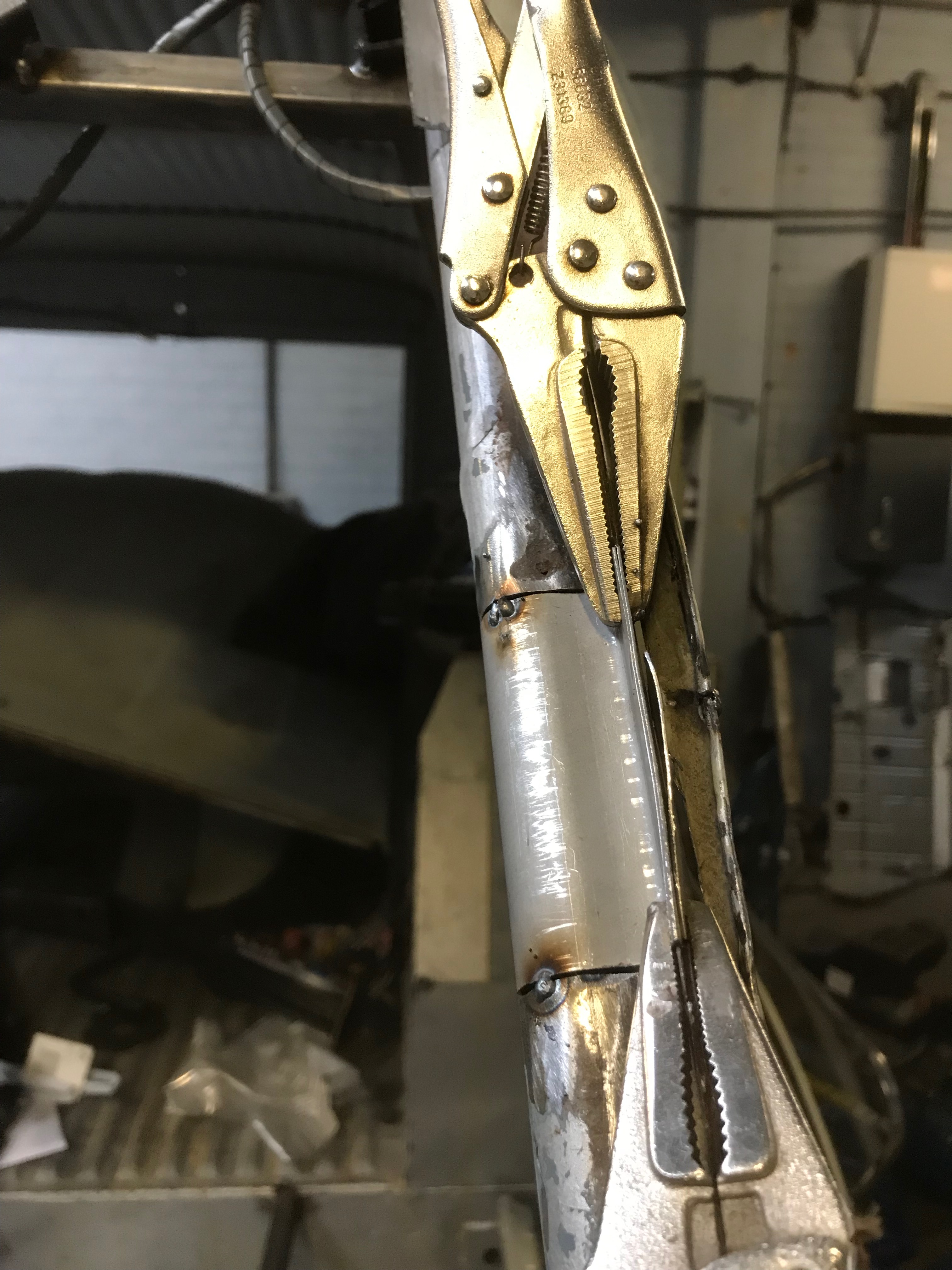
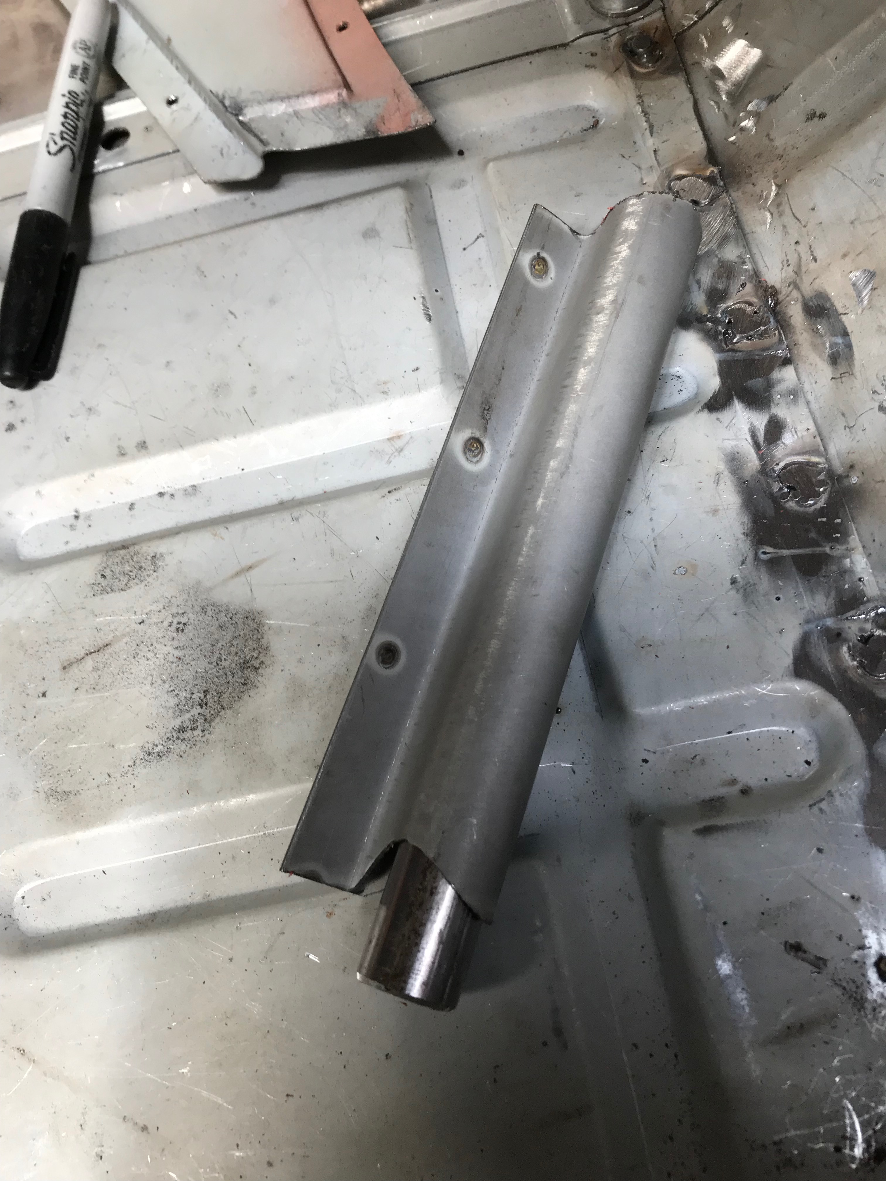
The A post repair section comes with a short lengh of tube, some rivnuts and a nut and bolt. The rivets and single nut bolt and 2 washers remain a total mystery to me – I’m sure they are included in the repair pack for some reason, but neither I, ECAS or the Dutch manufacturer of the parts were able to fathom out what that reason is, so I’ll just keep them in their little bag and then file them under B1N later. The tube is used to reinforce the join between the old and new A post sections, sliding neatly inside, it will give me something to weld to and minimise the risk of blowing a hole through where the join will be. I bought another metre of half inch tube (or ‘Toob’ as they say in Norfolk) as I’ll need a bit more than what was supplied with the repair section because I’ll be doing both sides.

Tube installed

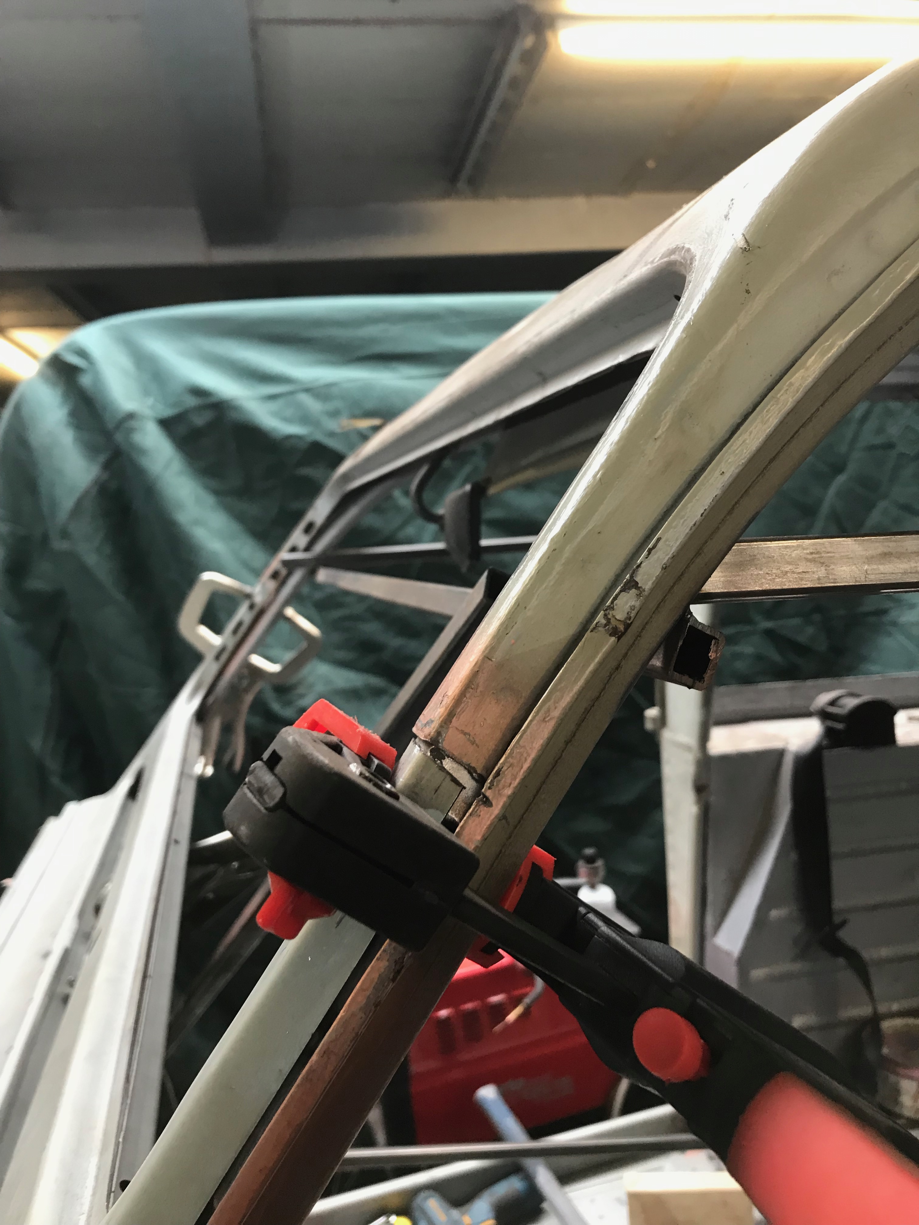
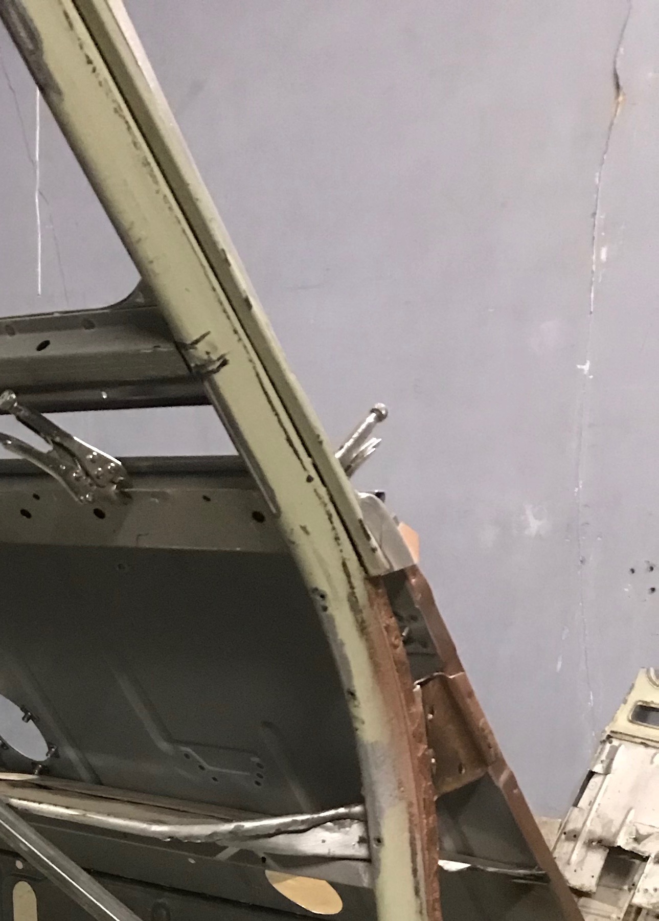
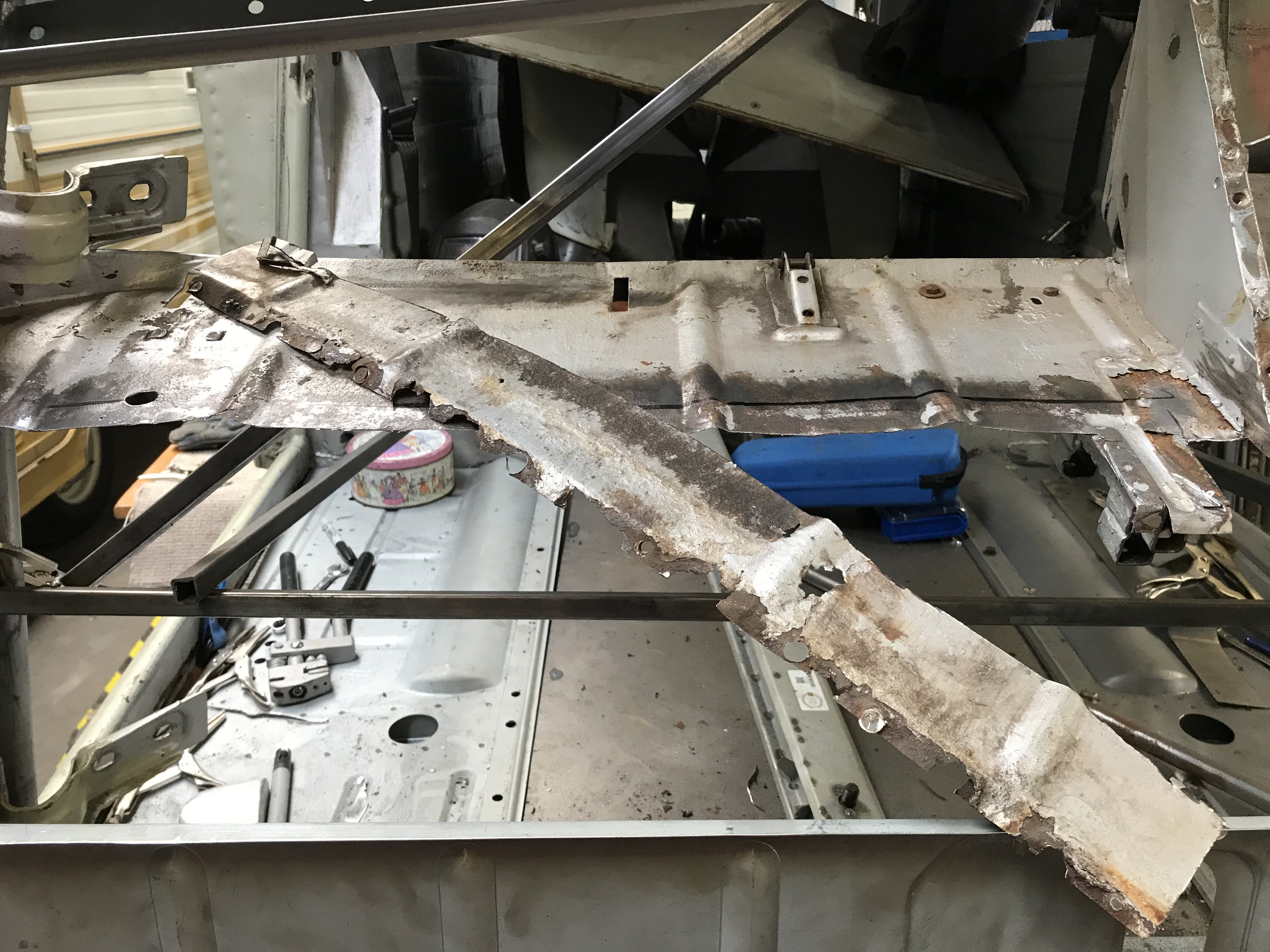
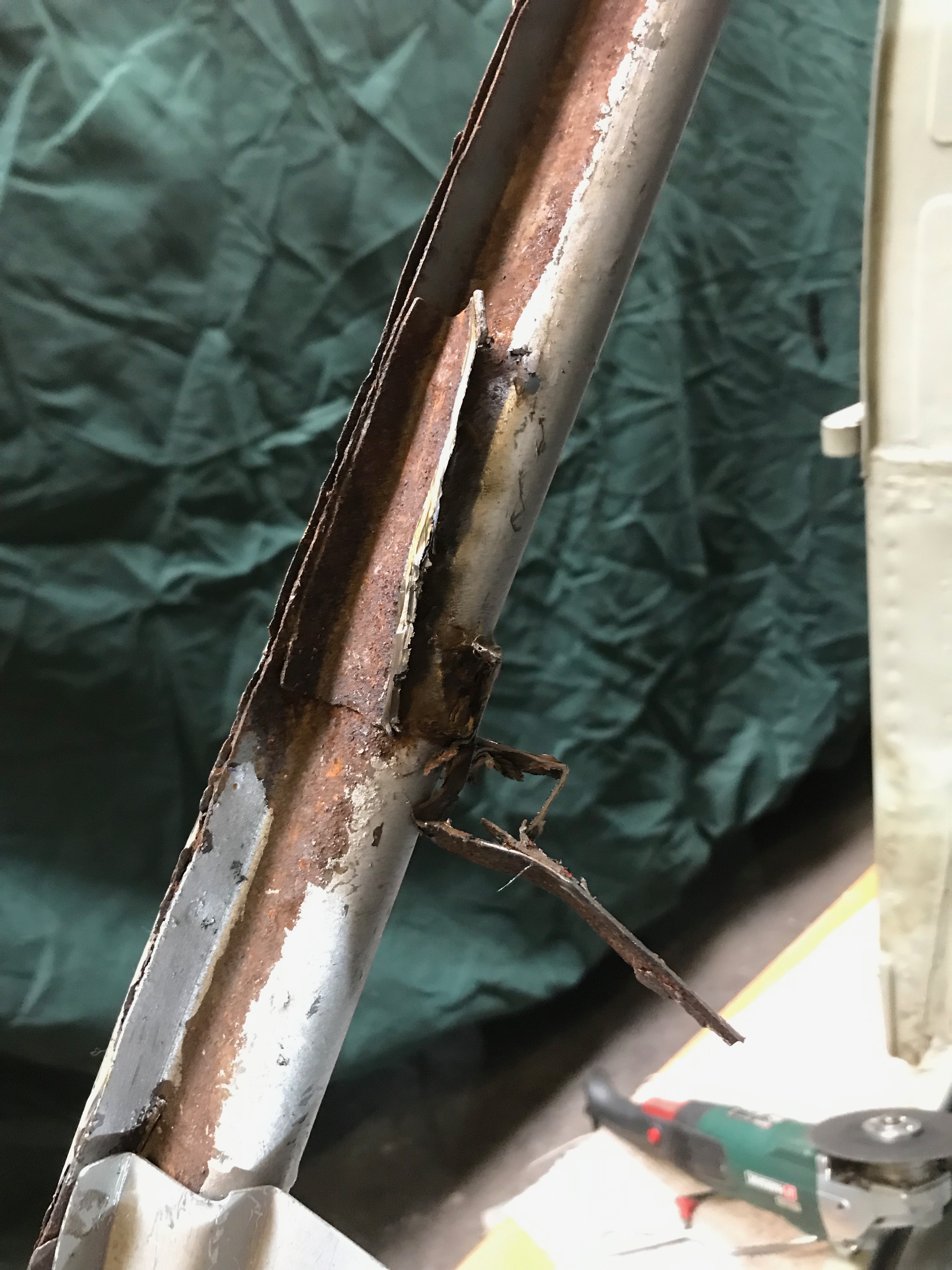
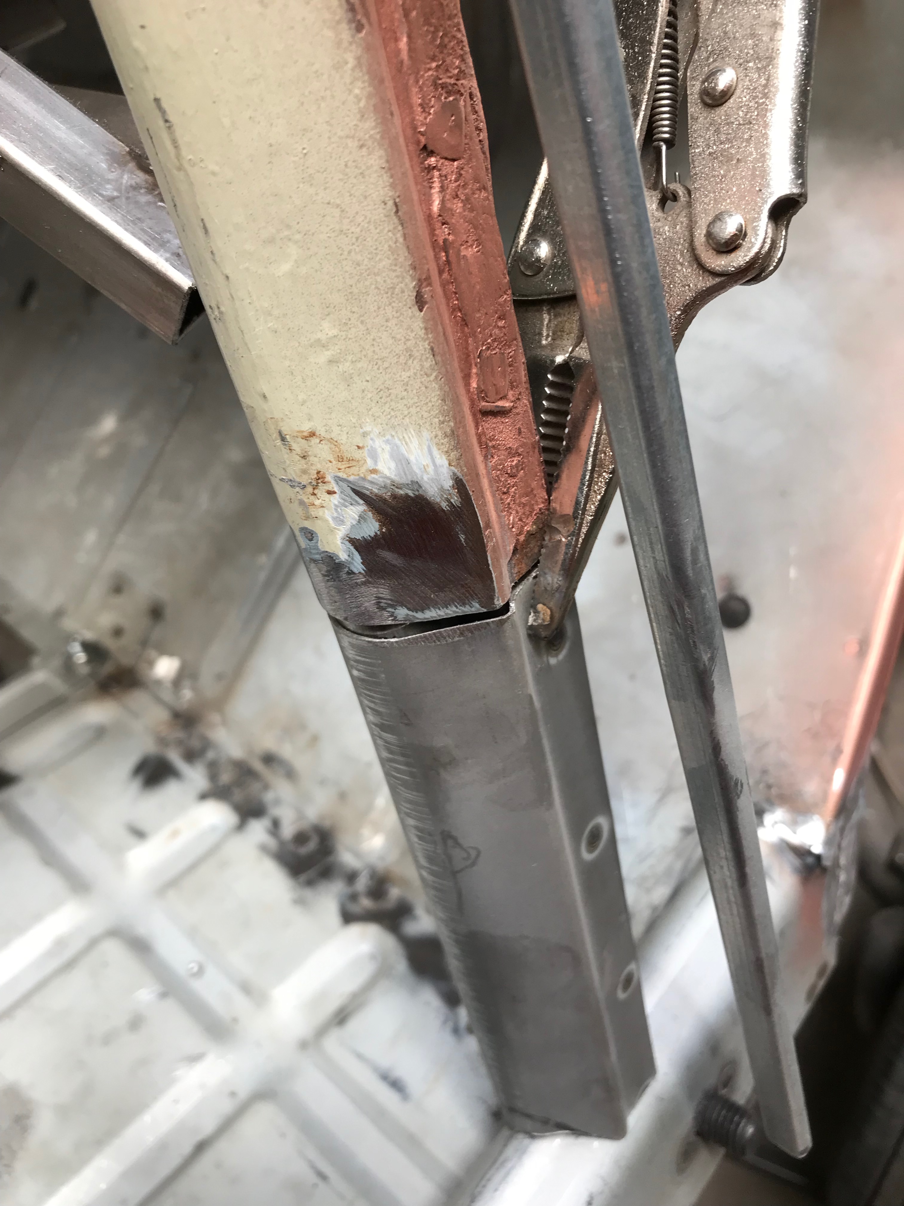
Here’s the bit of A post, ready to bridge the gap where I chopped out the rotten section. I spent a good 10 mins on the grinder wheel, shaping the bottom of the A post where it joins the sill.

Clamped up and ready to weld

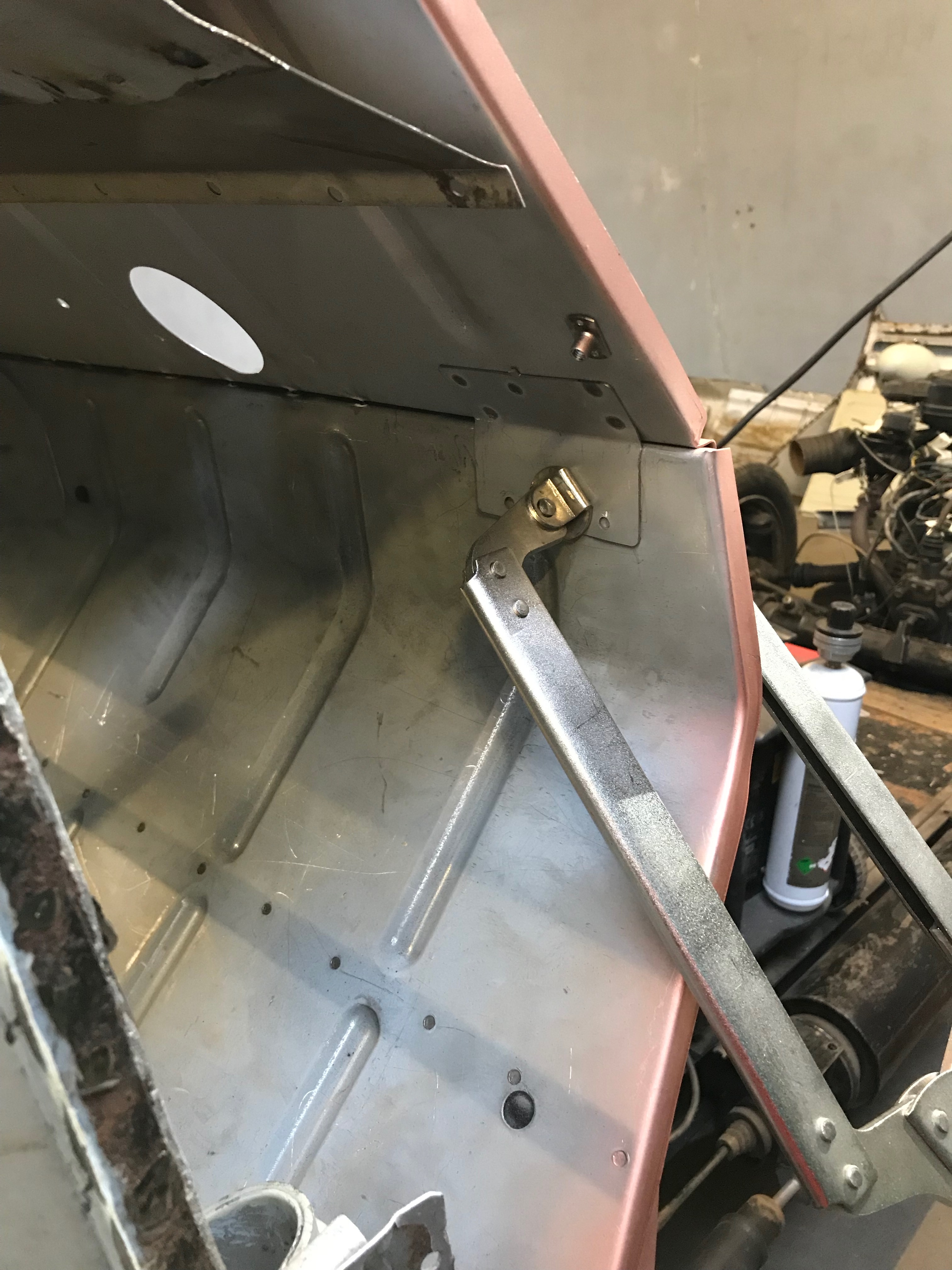
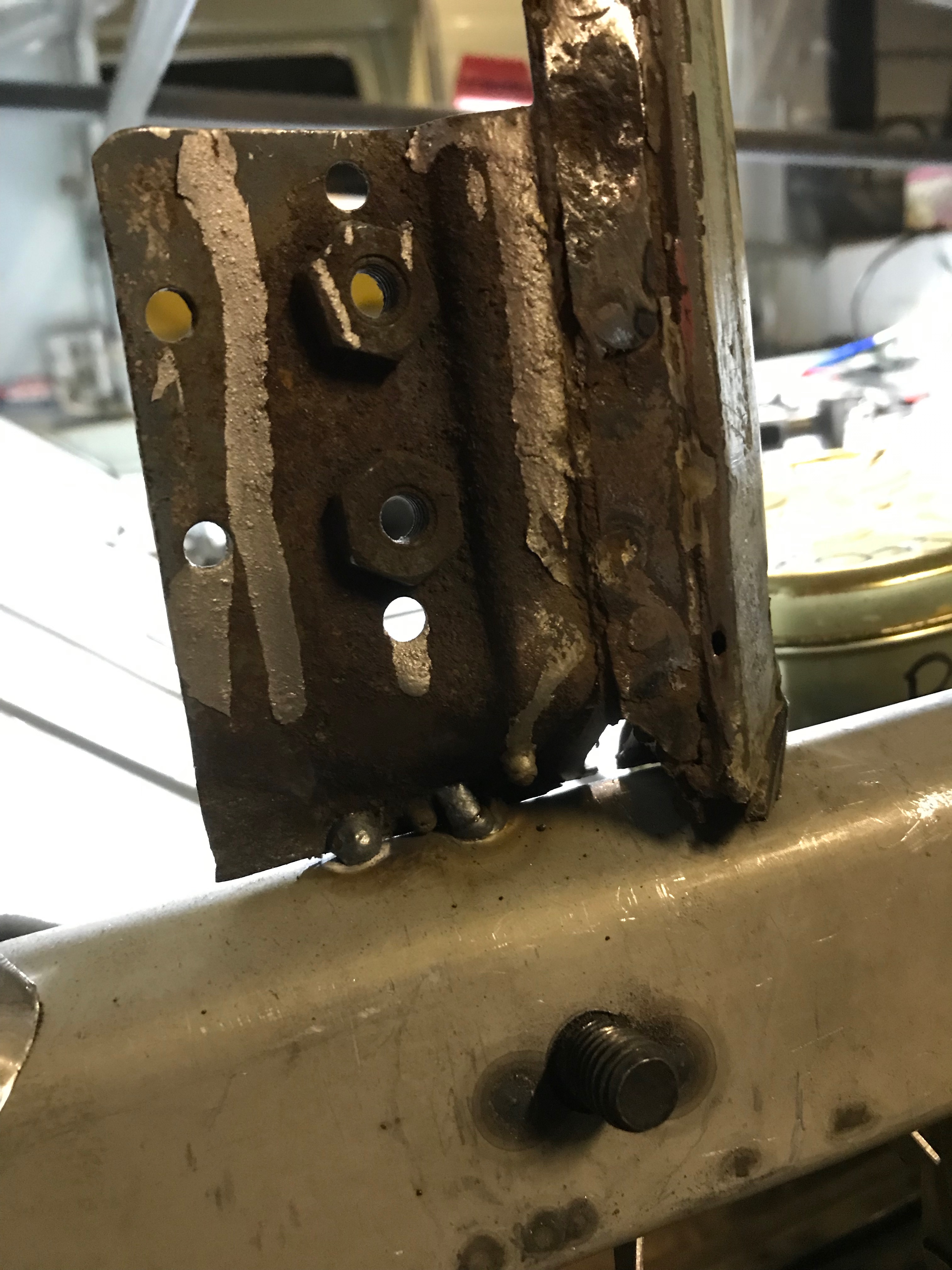
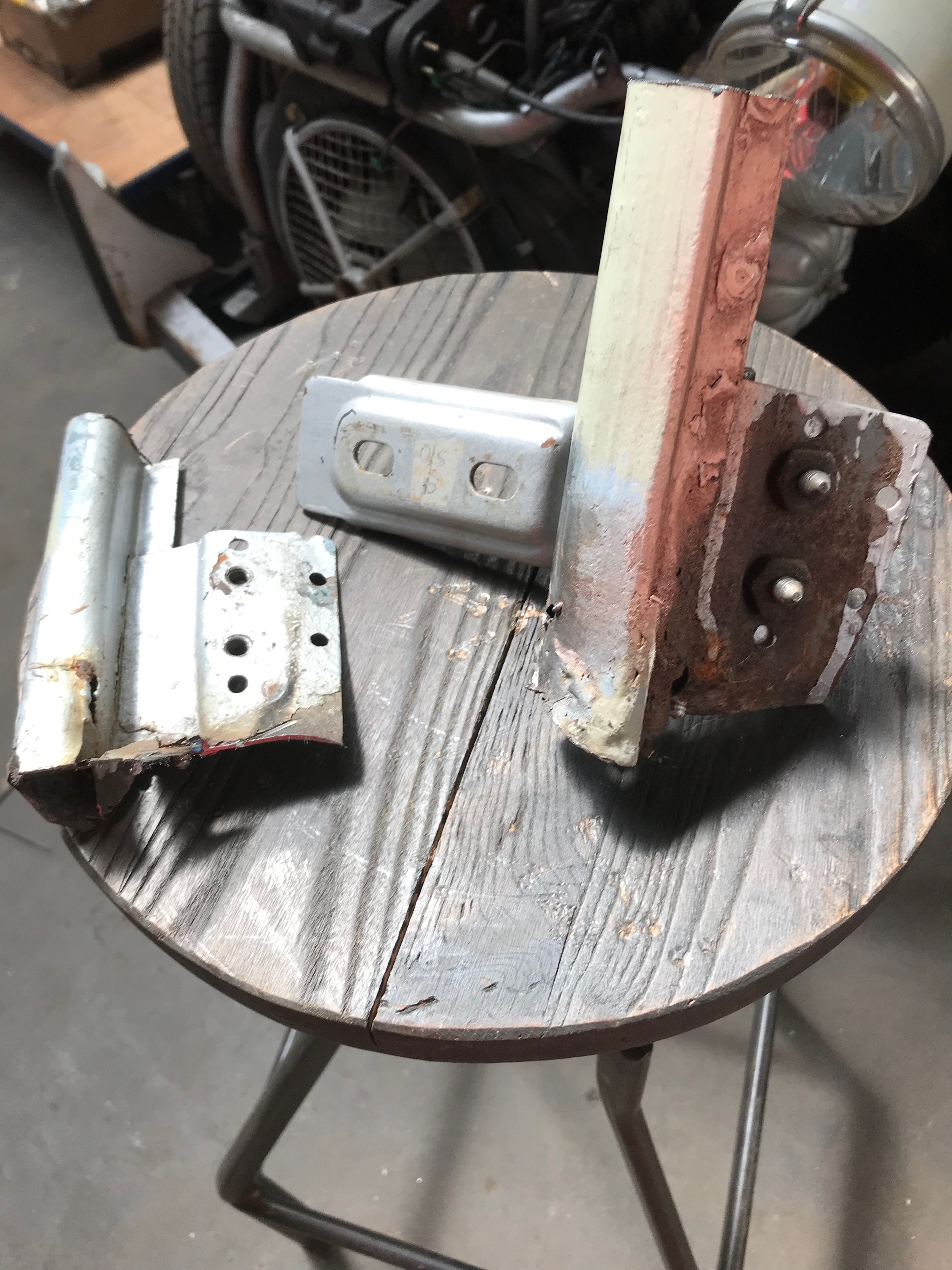
There’s no point in trying to salvage the bottom hinge brackets – the bits of steel which the hinges bolt to as they have been repaired once already and will become hoplessly out of shape if I try and cut them off and we reweld them. I have a pair of replacements ready…

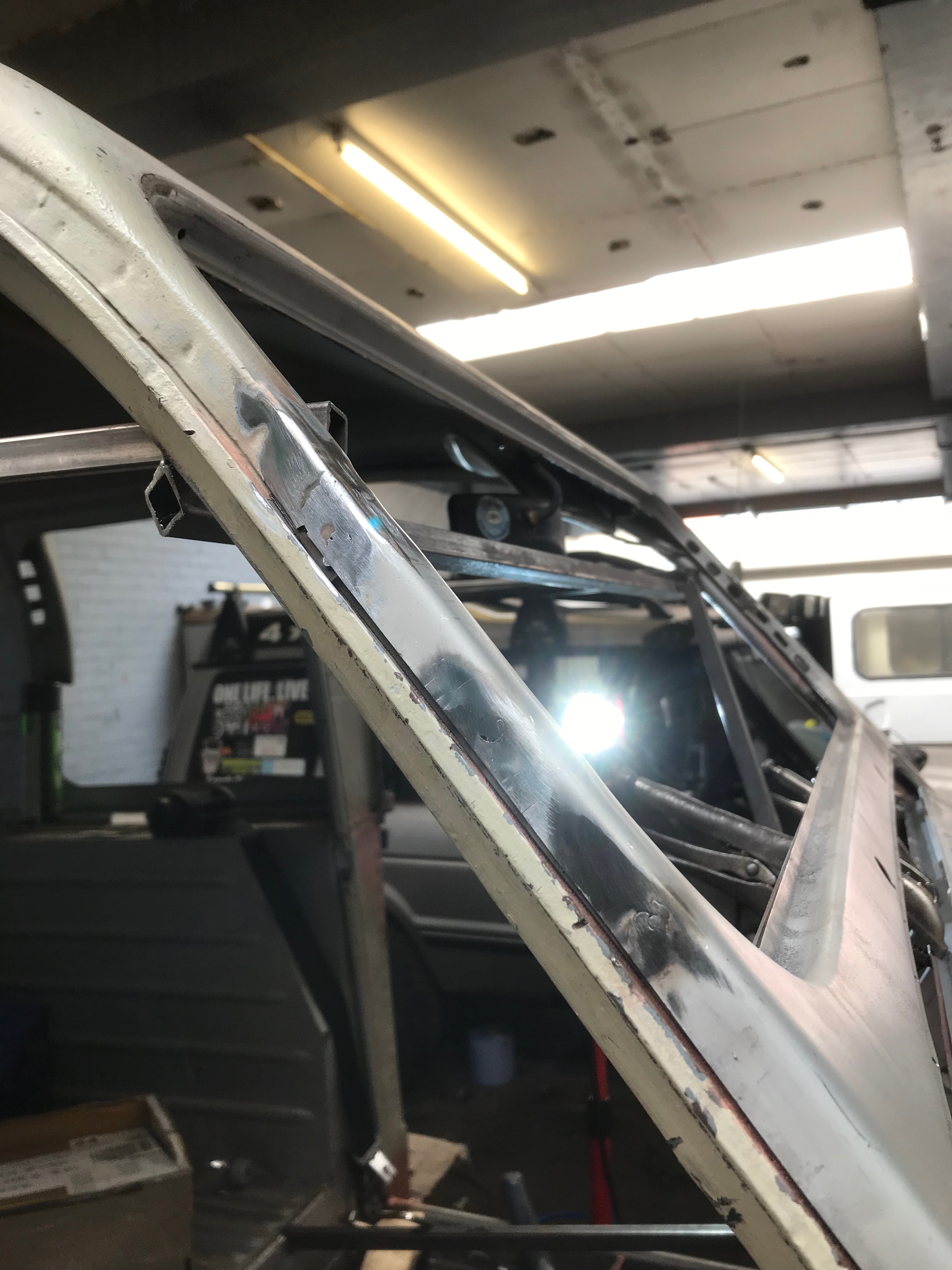
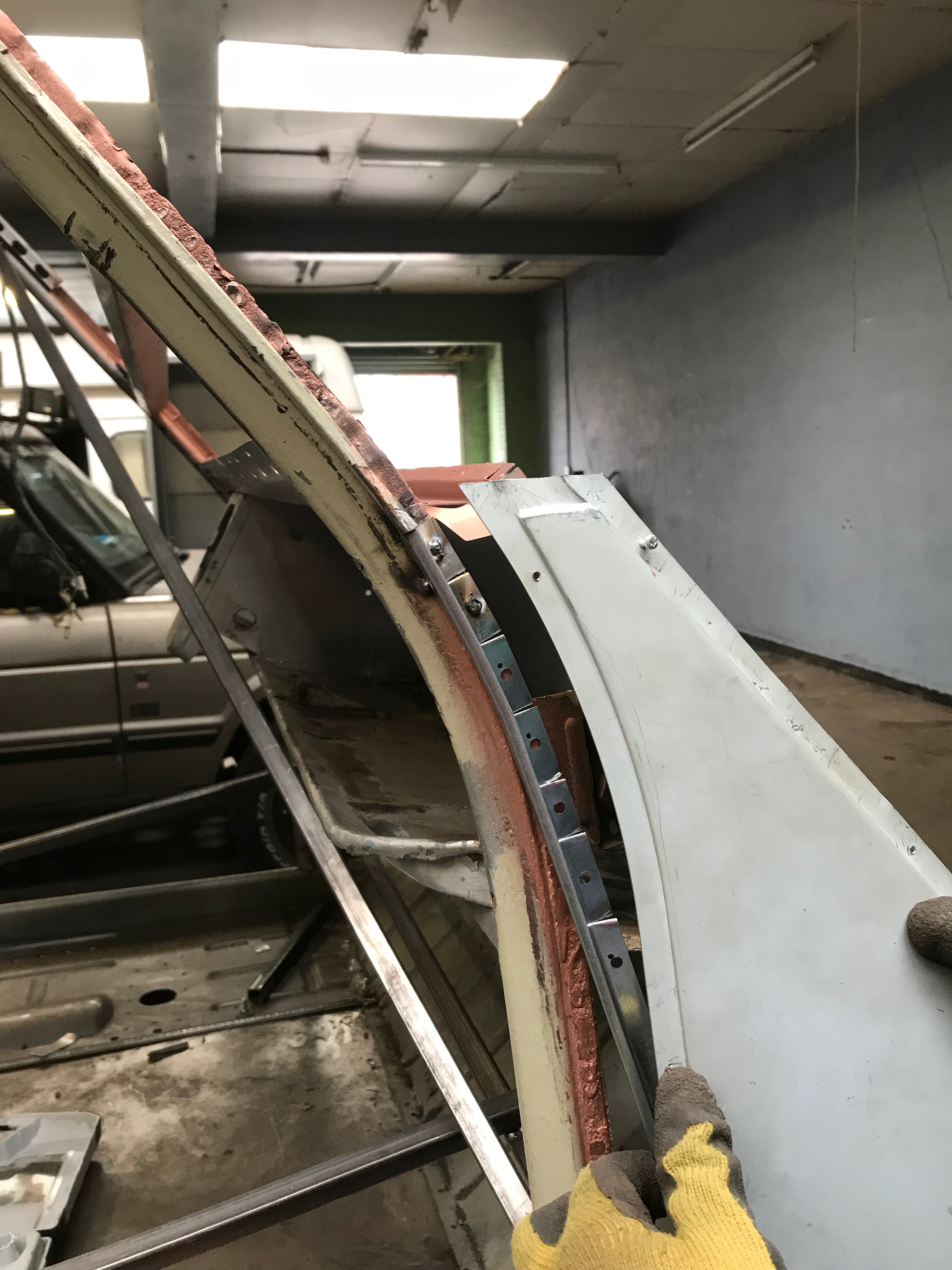
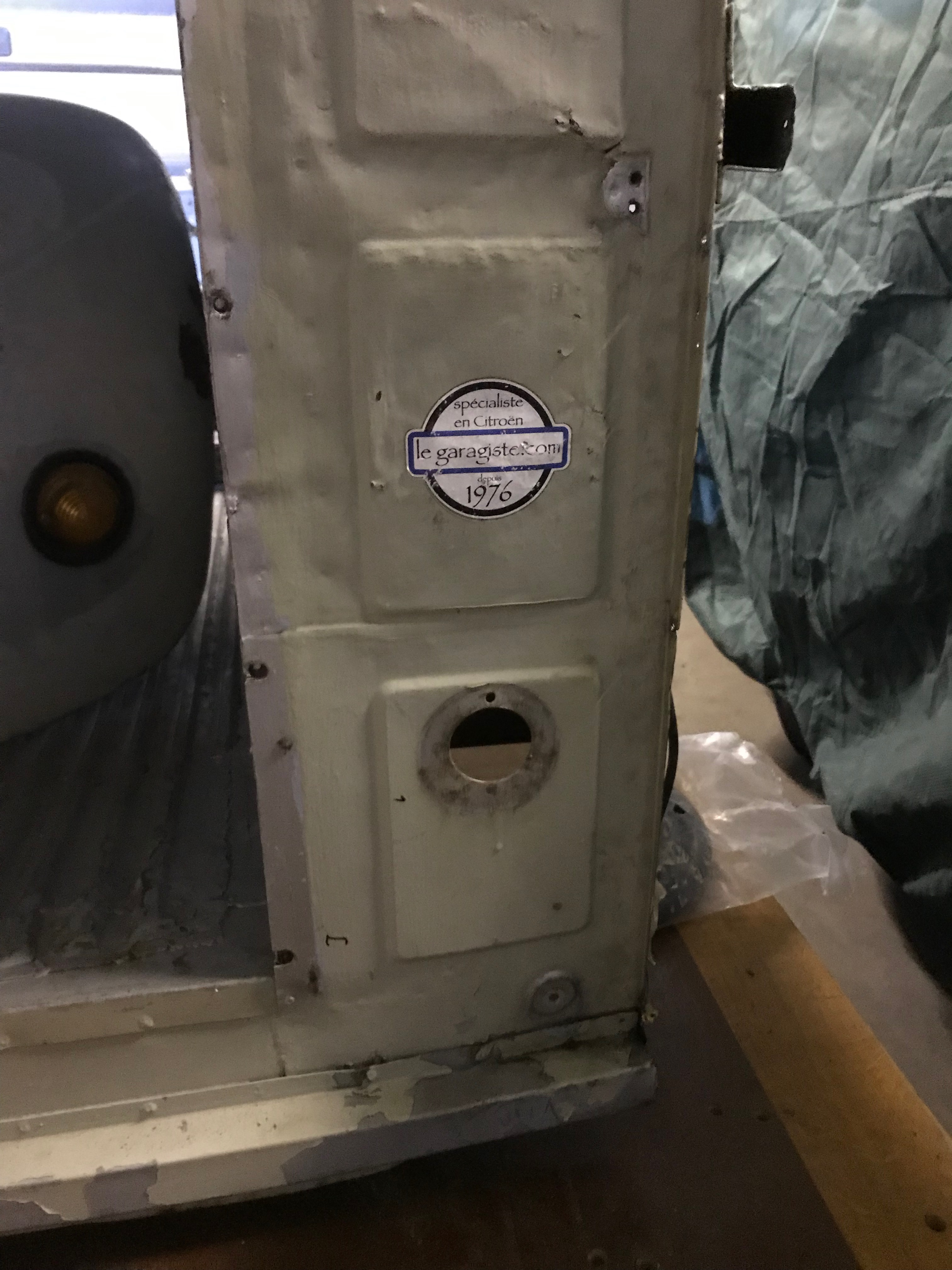
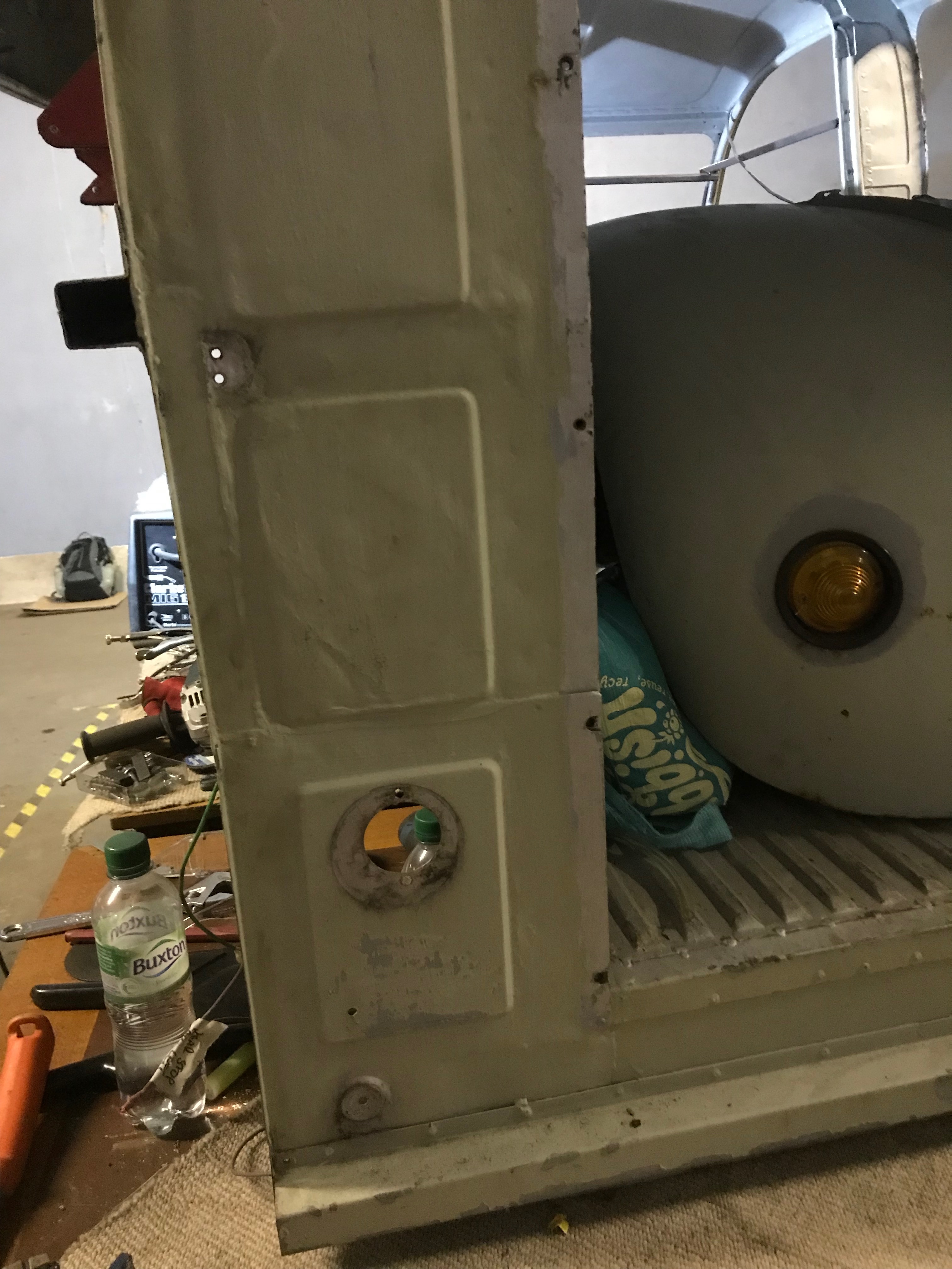
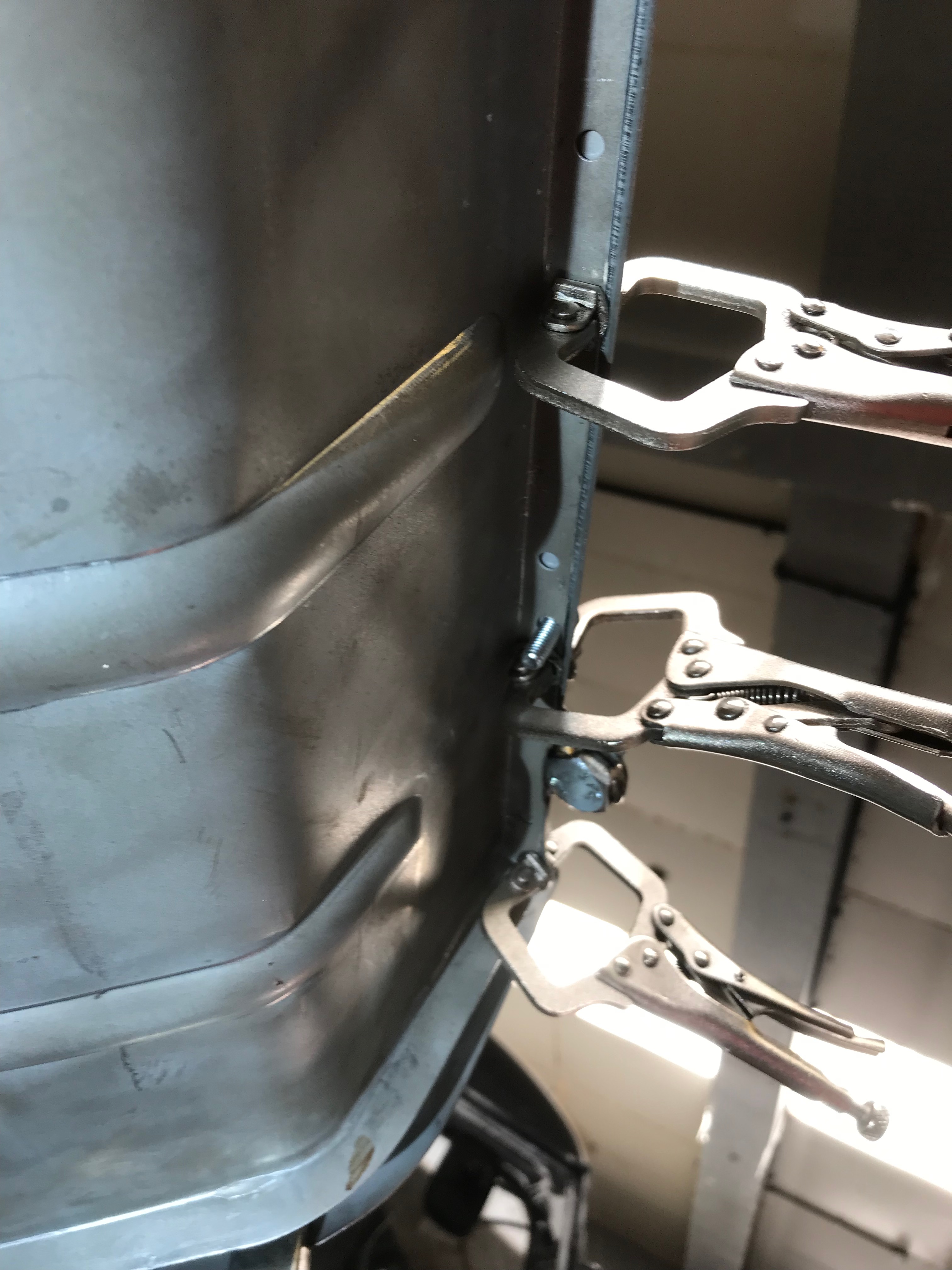
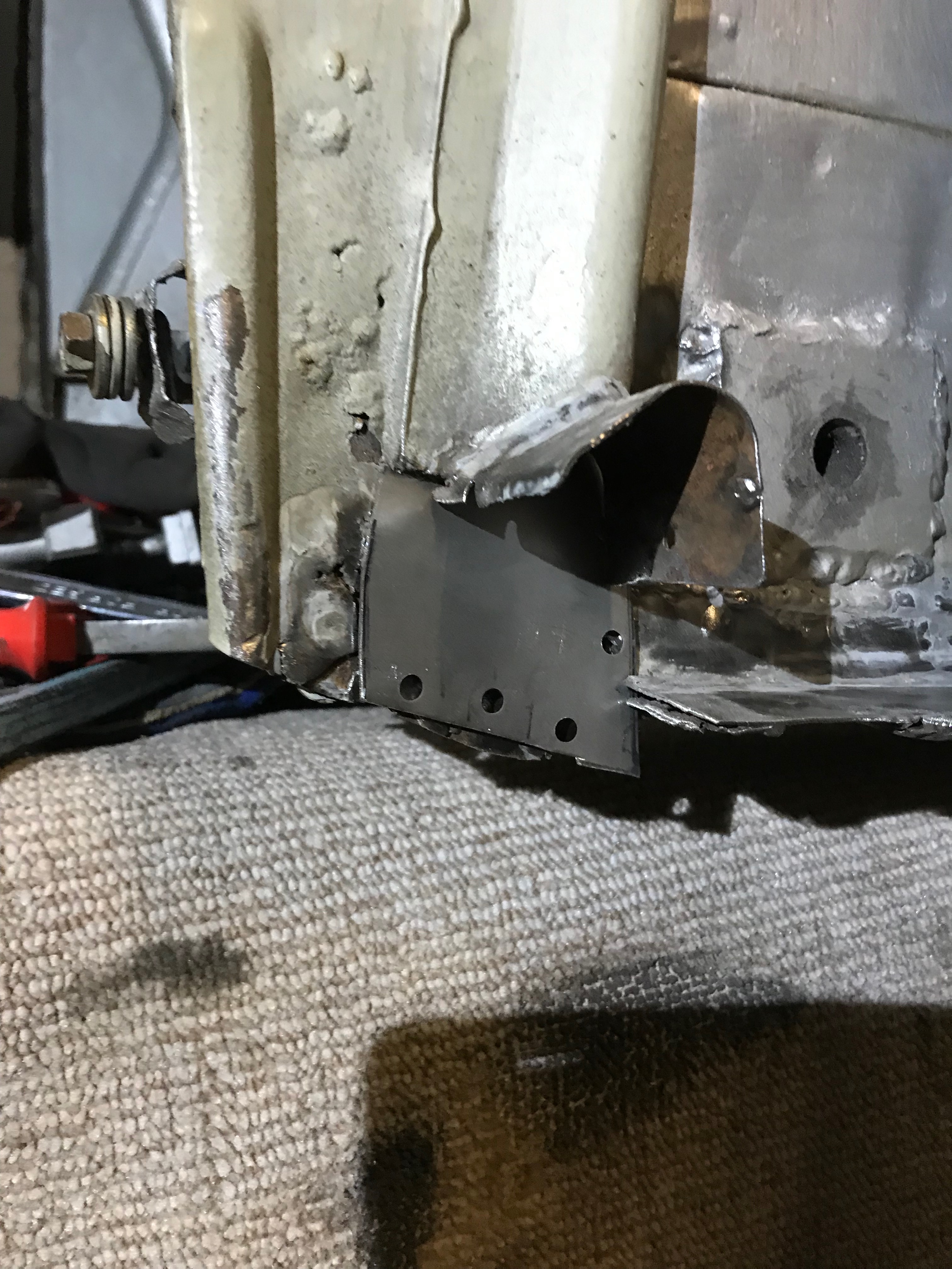
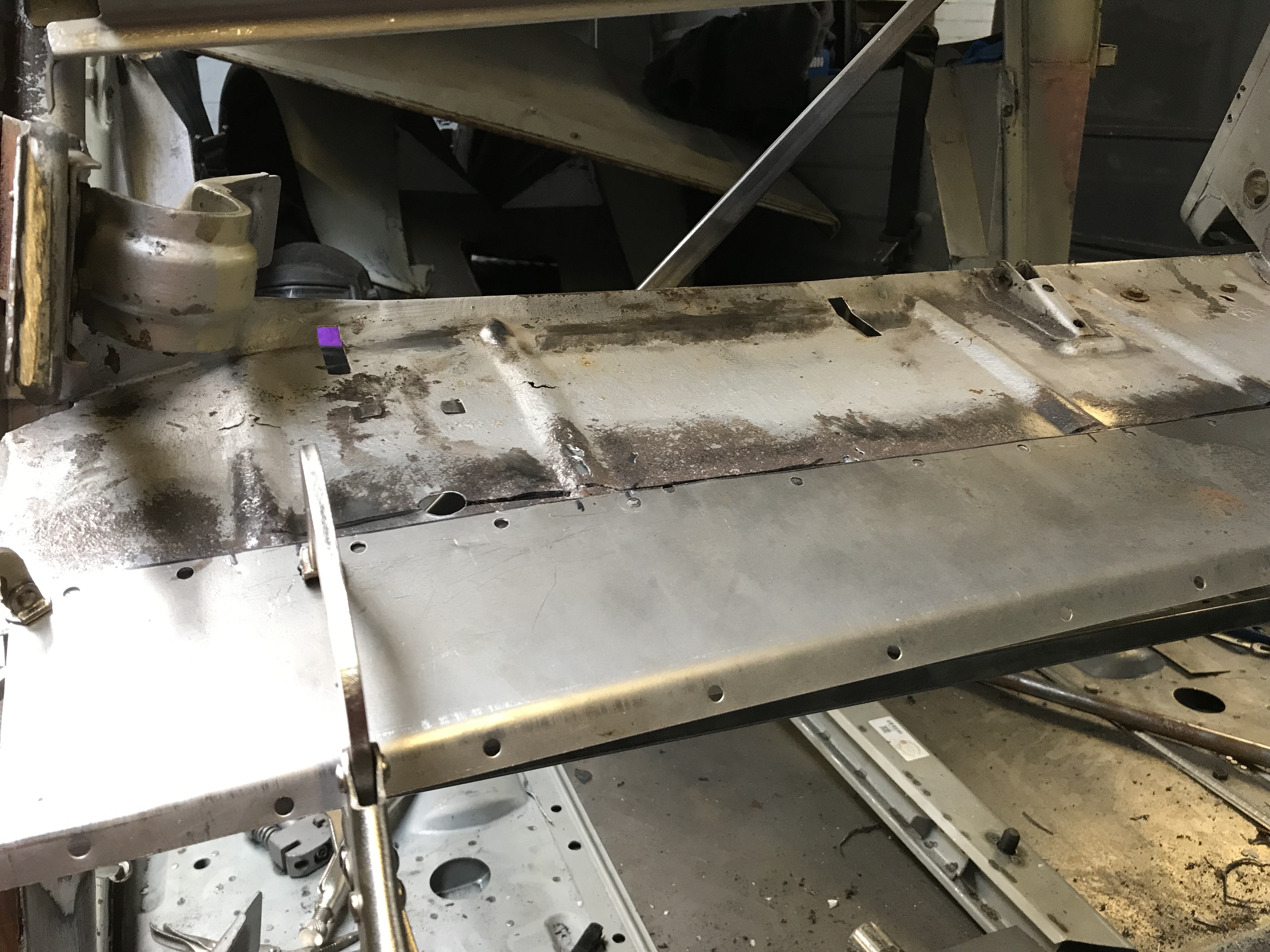
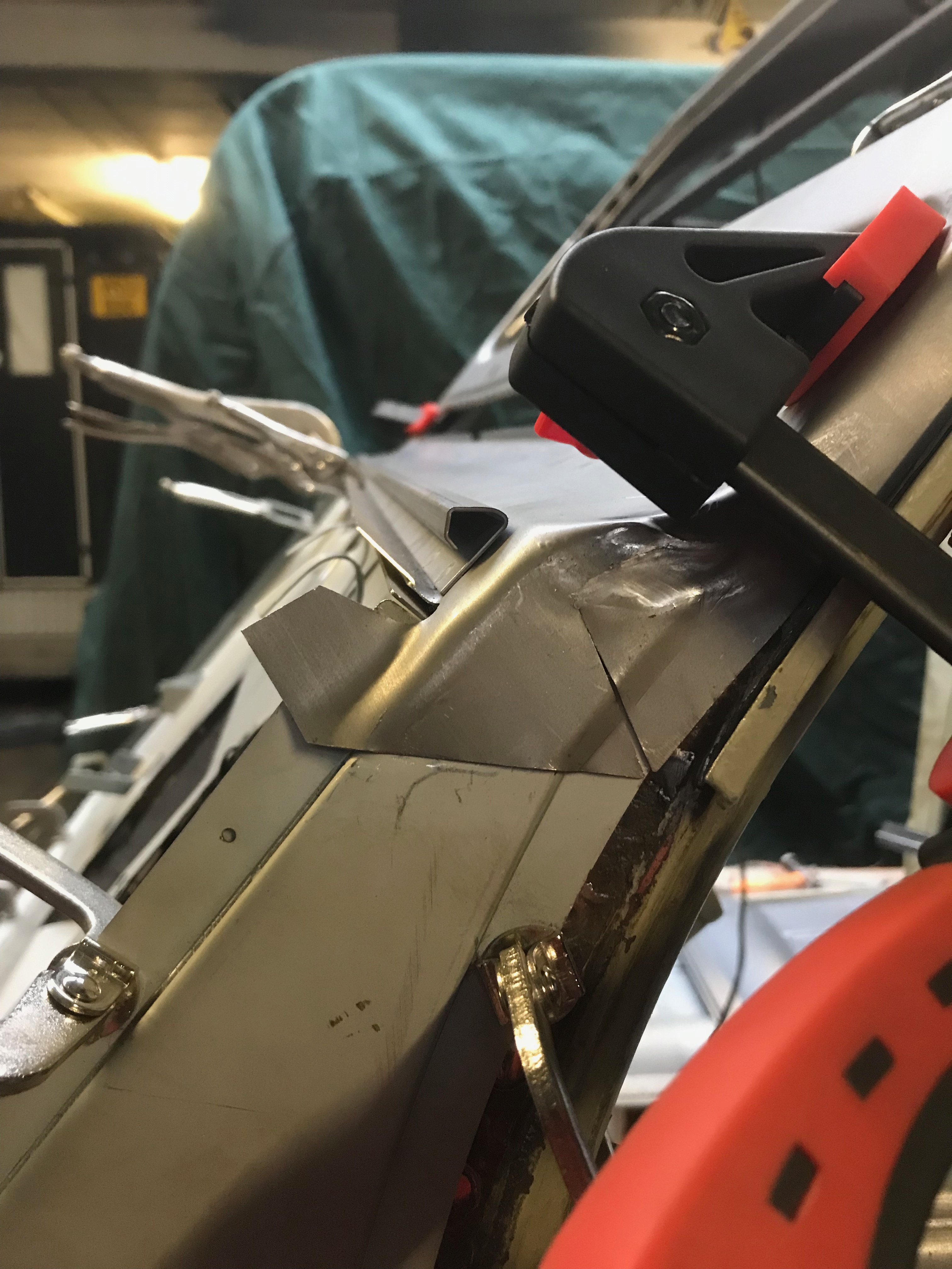
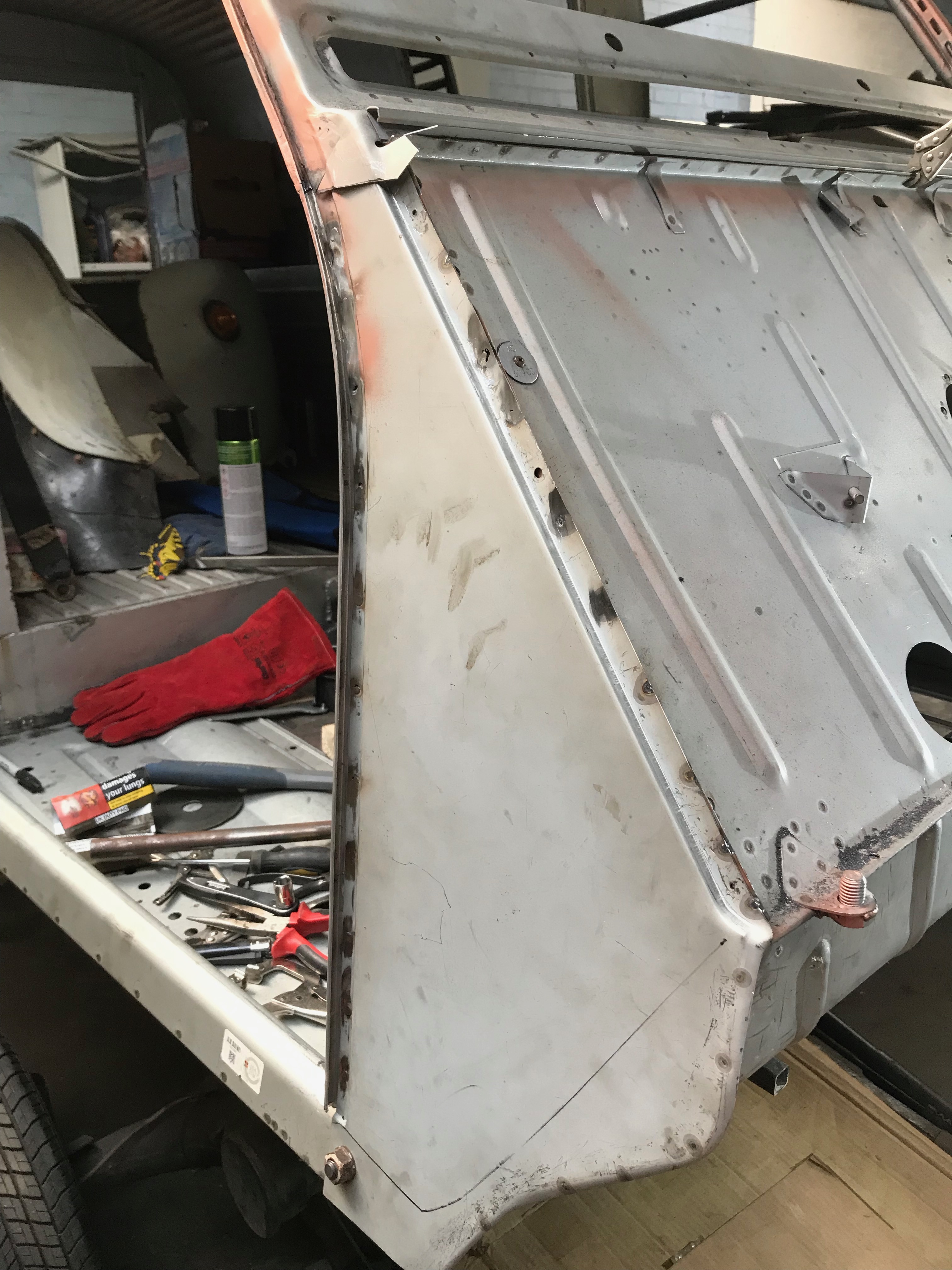
You can see below where I’ve stitched in the A post repair section and welded the bottom of it to the sill. This required a bit of dressing with the flap wheel and grinder but all in all has gone quite well. It’ll need a skim of filler to tidy it up properly. I used the A panel as a template to line everything up – top tip!

Here’s the panel clamp up for alignment – I marked the line where the wing joins it so that any plug welds can be hidden when the wing is fitted

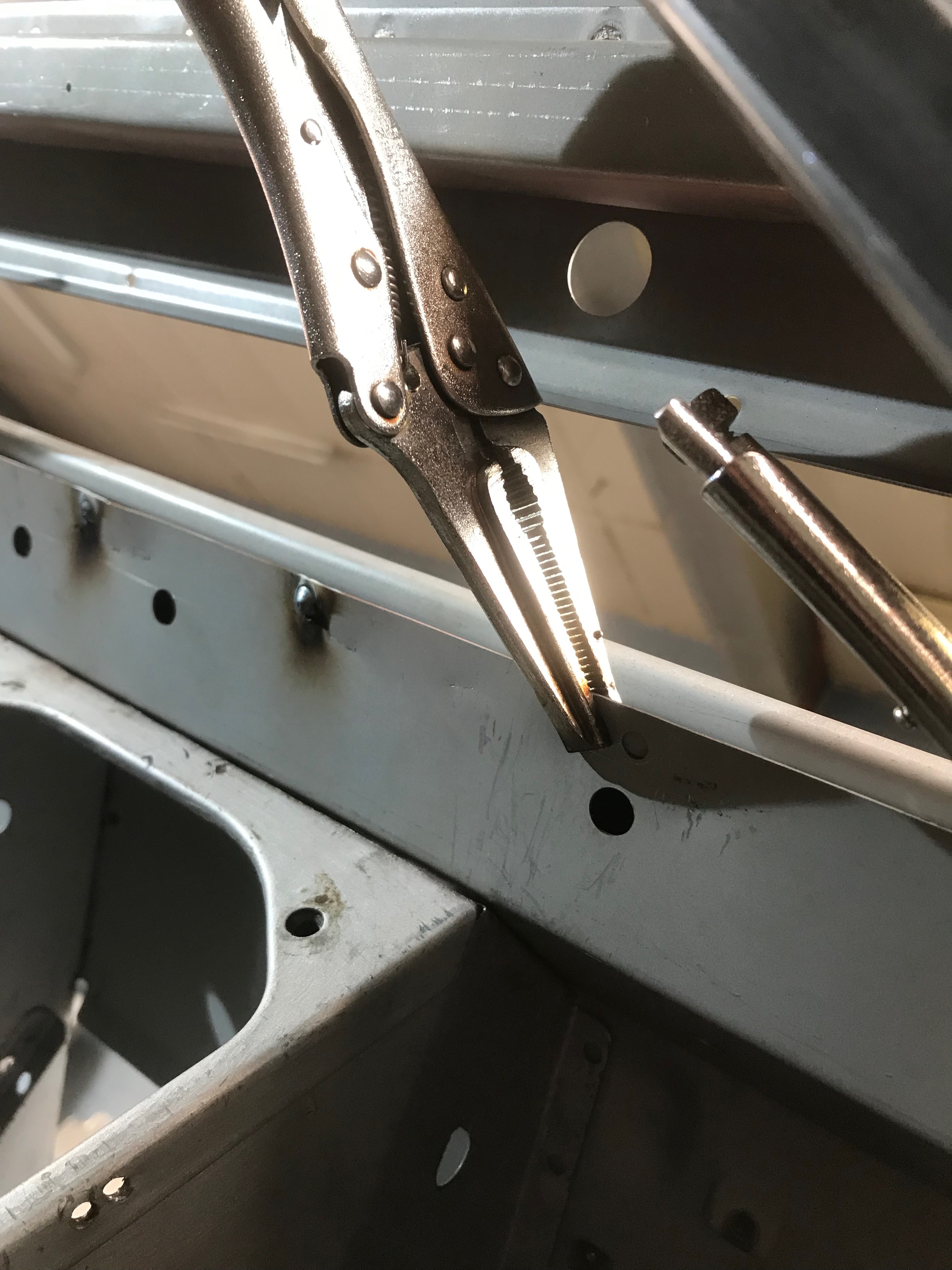
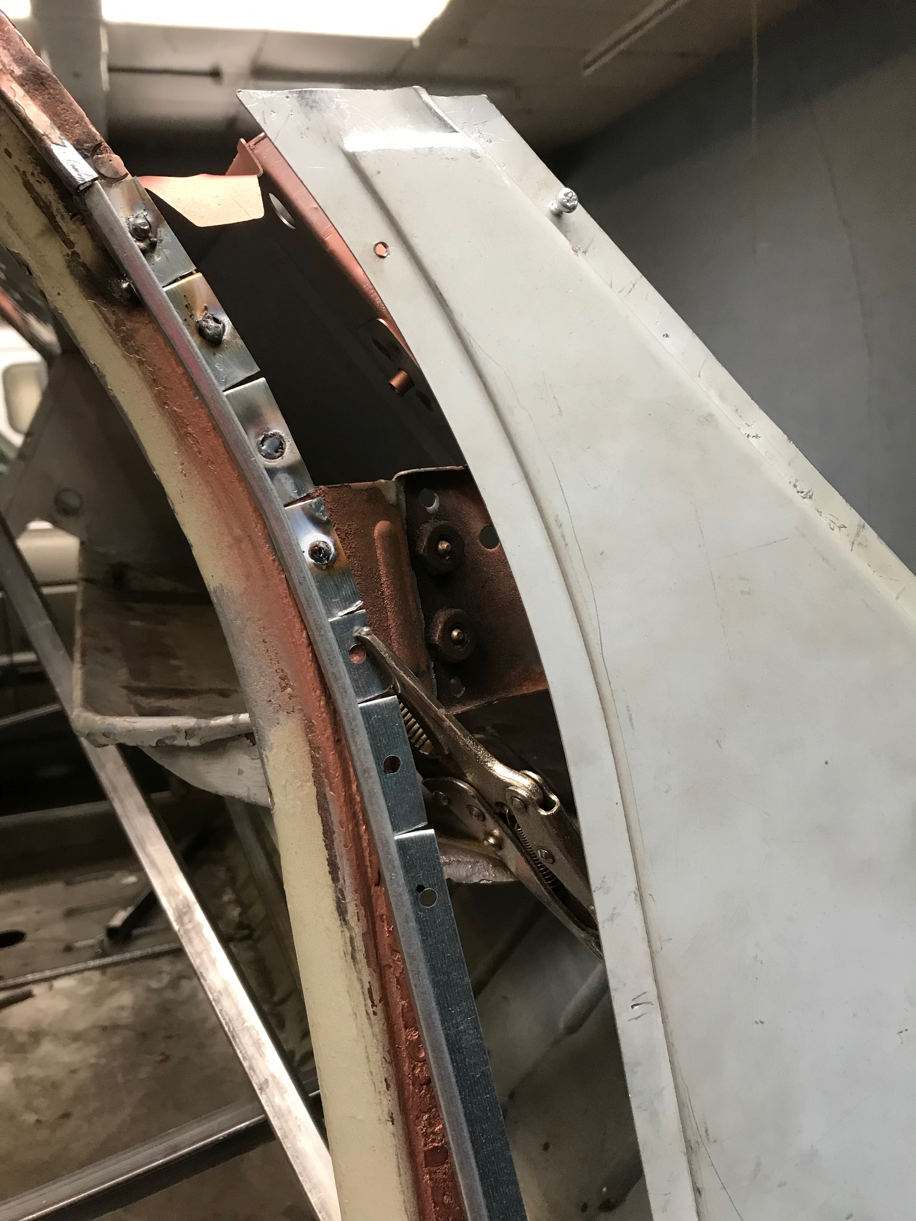
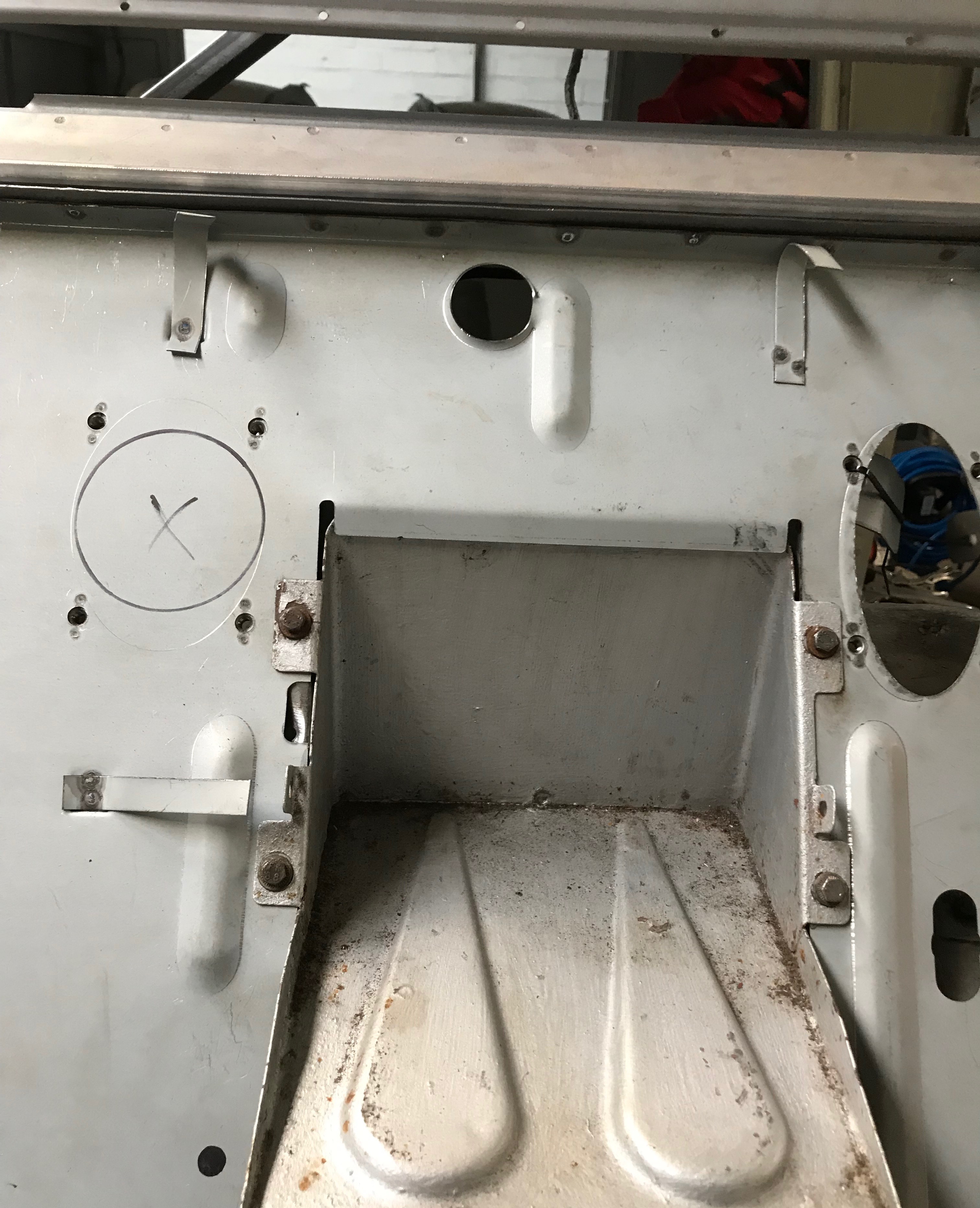
This is the inside edge of the A panel – once welded the flange will be folded over to close the join.

Folding over the flange

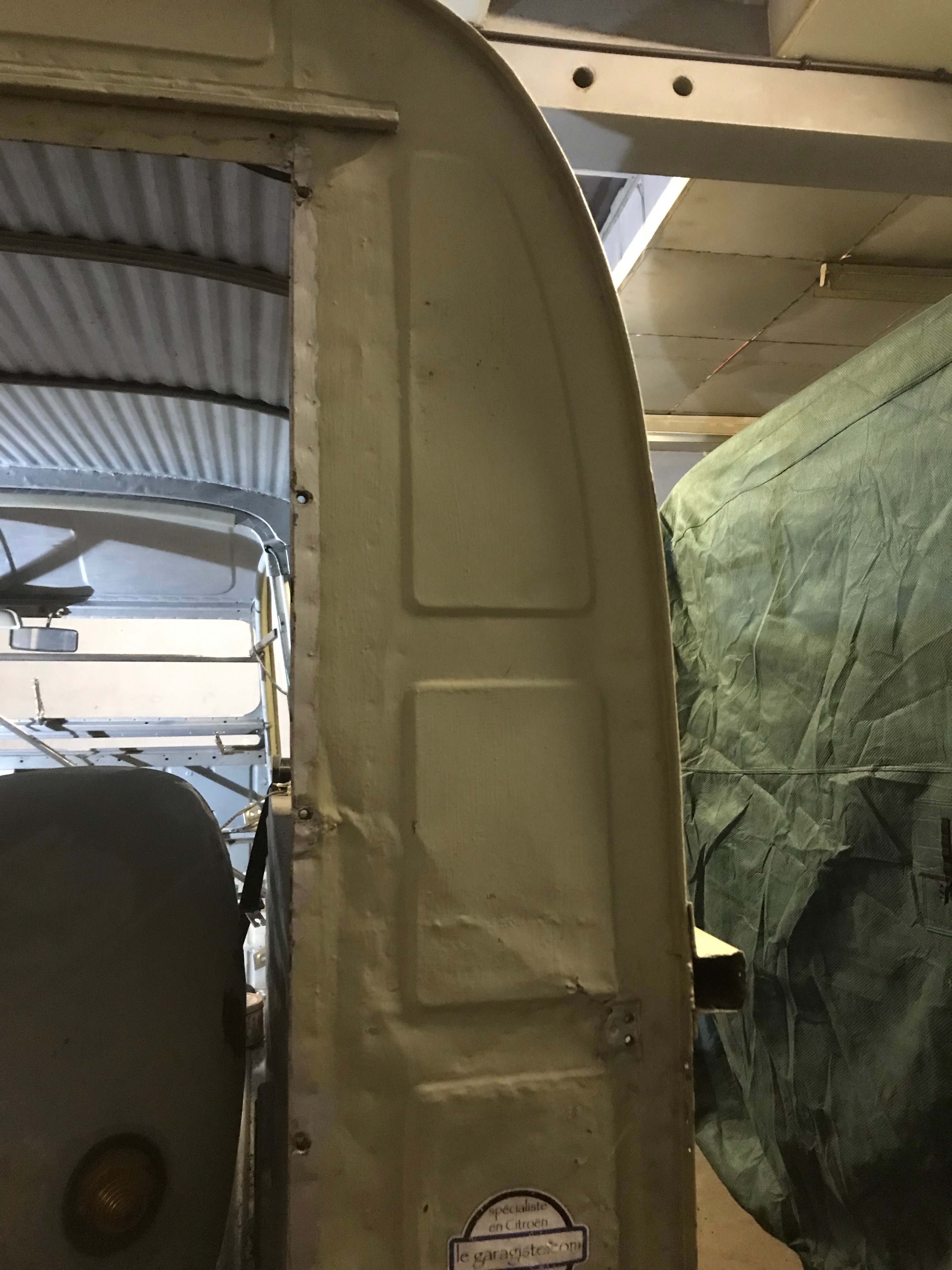
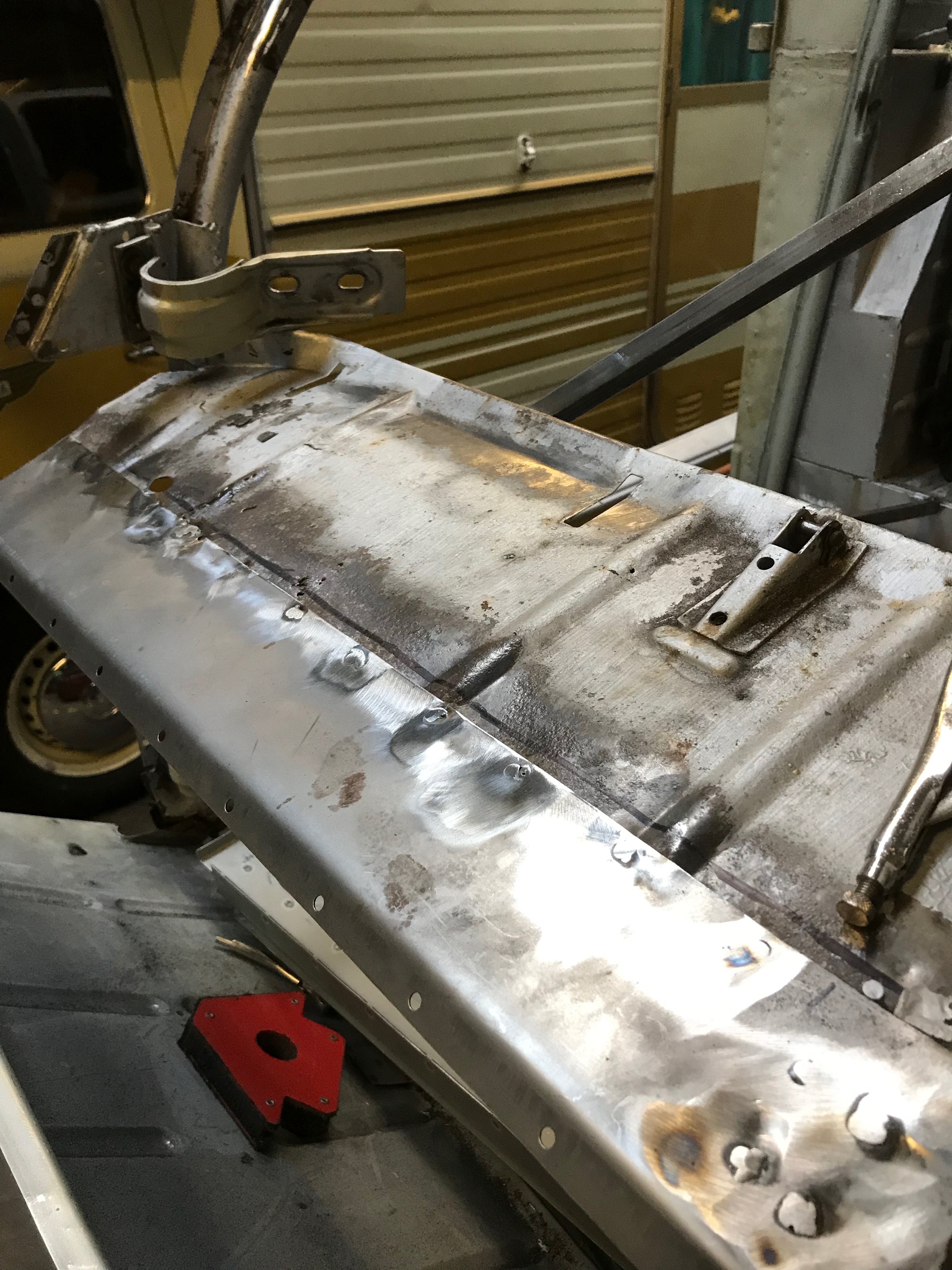
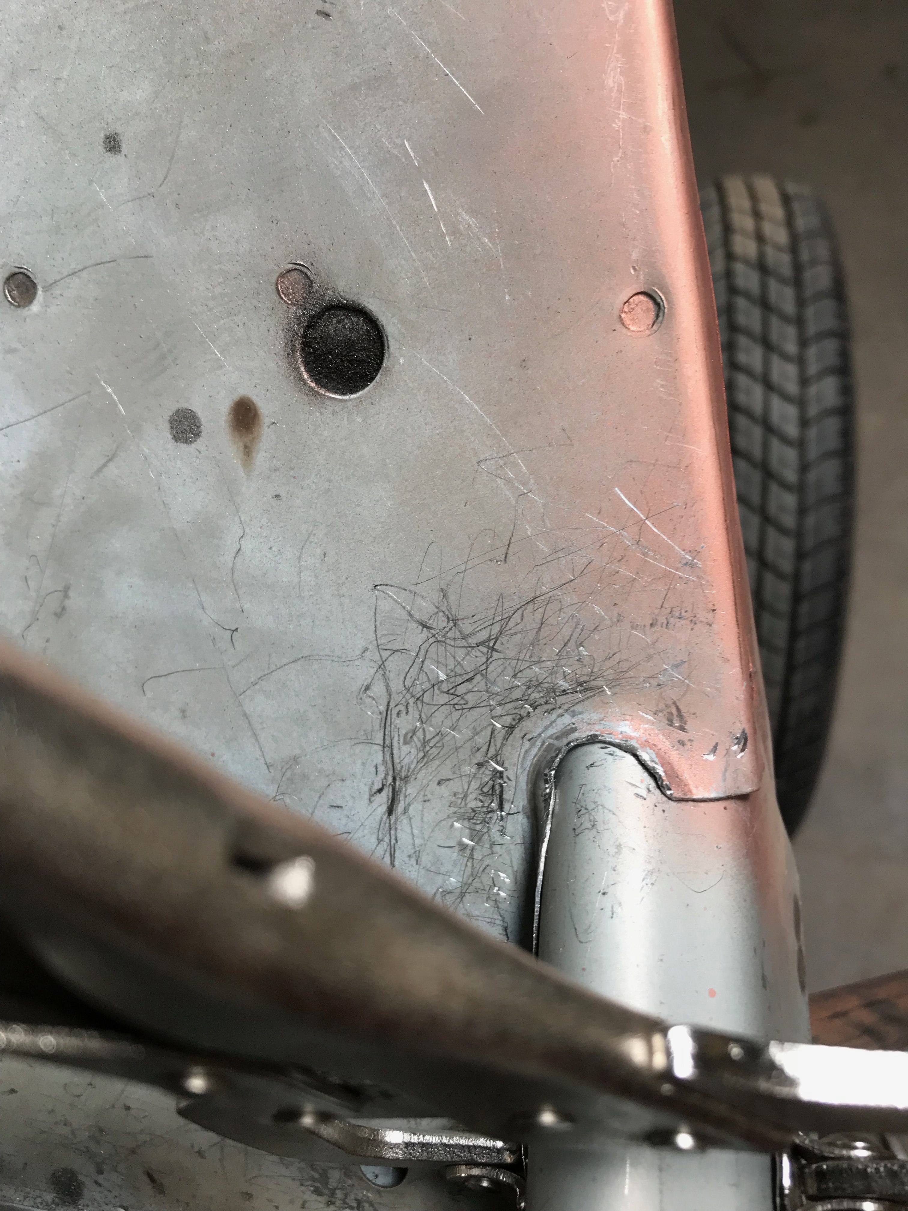
I folded the edge over with a panel beating hammer and dolly. The trick is not to overwork the steel, the more you bash it, the harder it becomes. It’s took a while to finish this off but eventually I managed it. Below is the A panel fitted, with plug welds to join it to the firewall and all the way down the A post to the sill. A bit of seam sealer will be needed inside the gutter as this is exposed to the elements.

The top (apex) of the A panel is not yet welded. I think it will be better to braze it, rather than seam weld. The flap of metal sticking out will be folded around the top of the firewall.

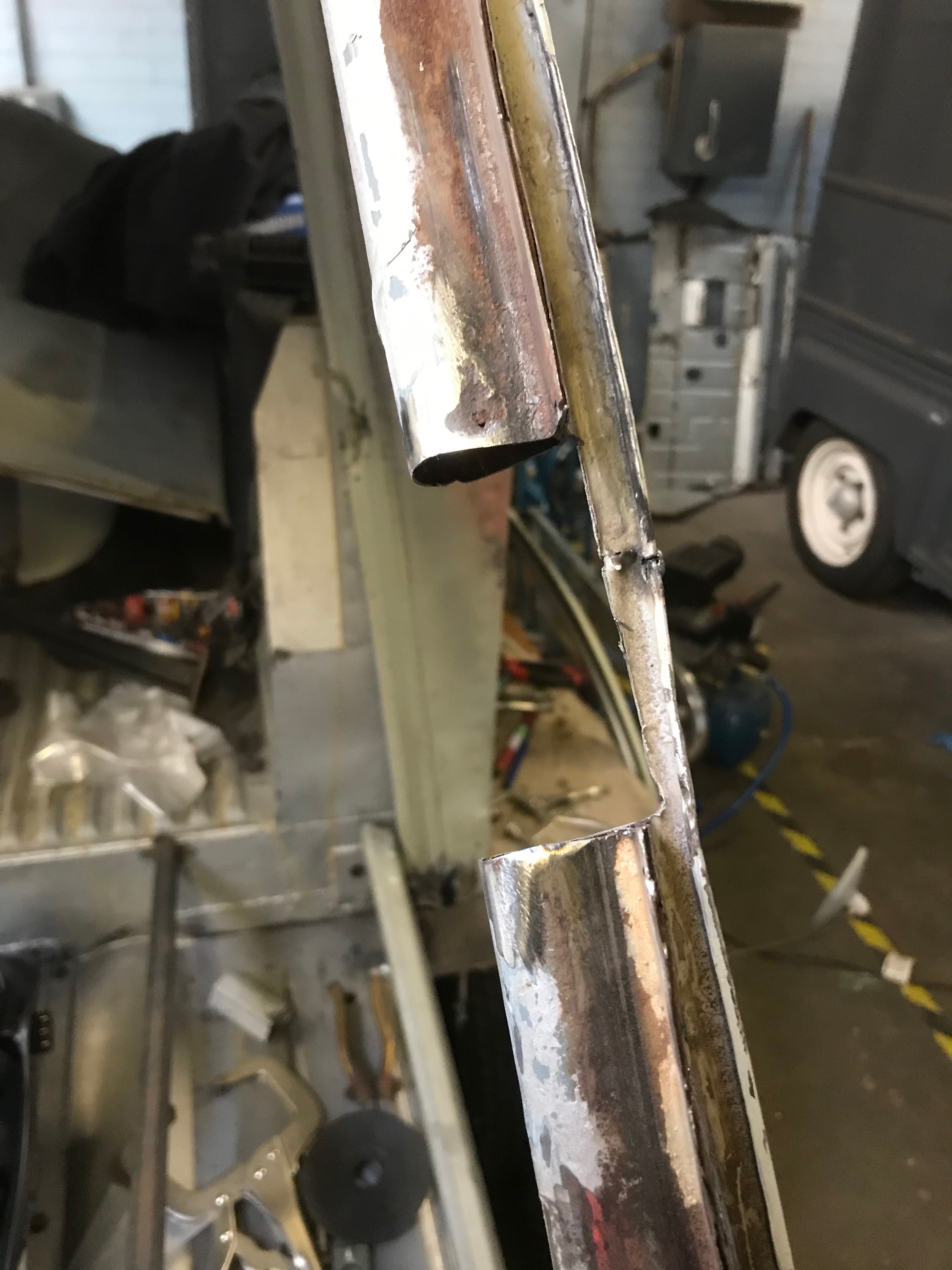
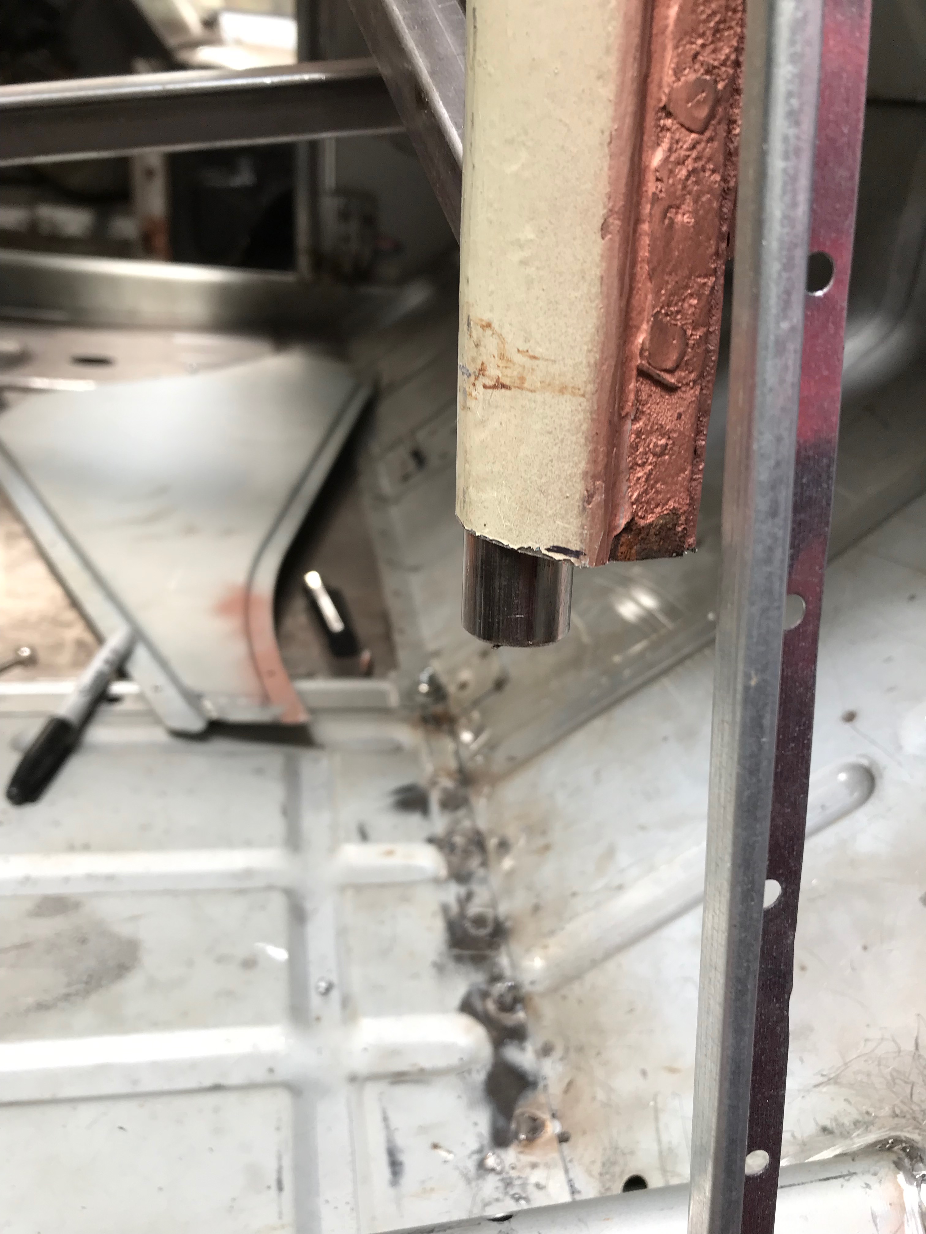
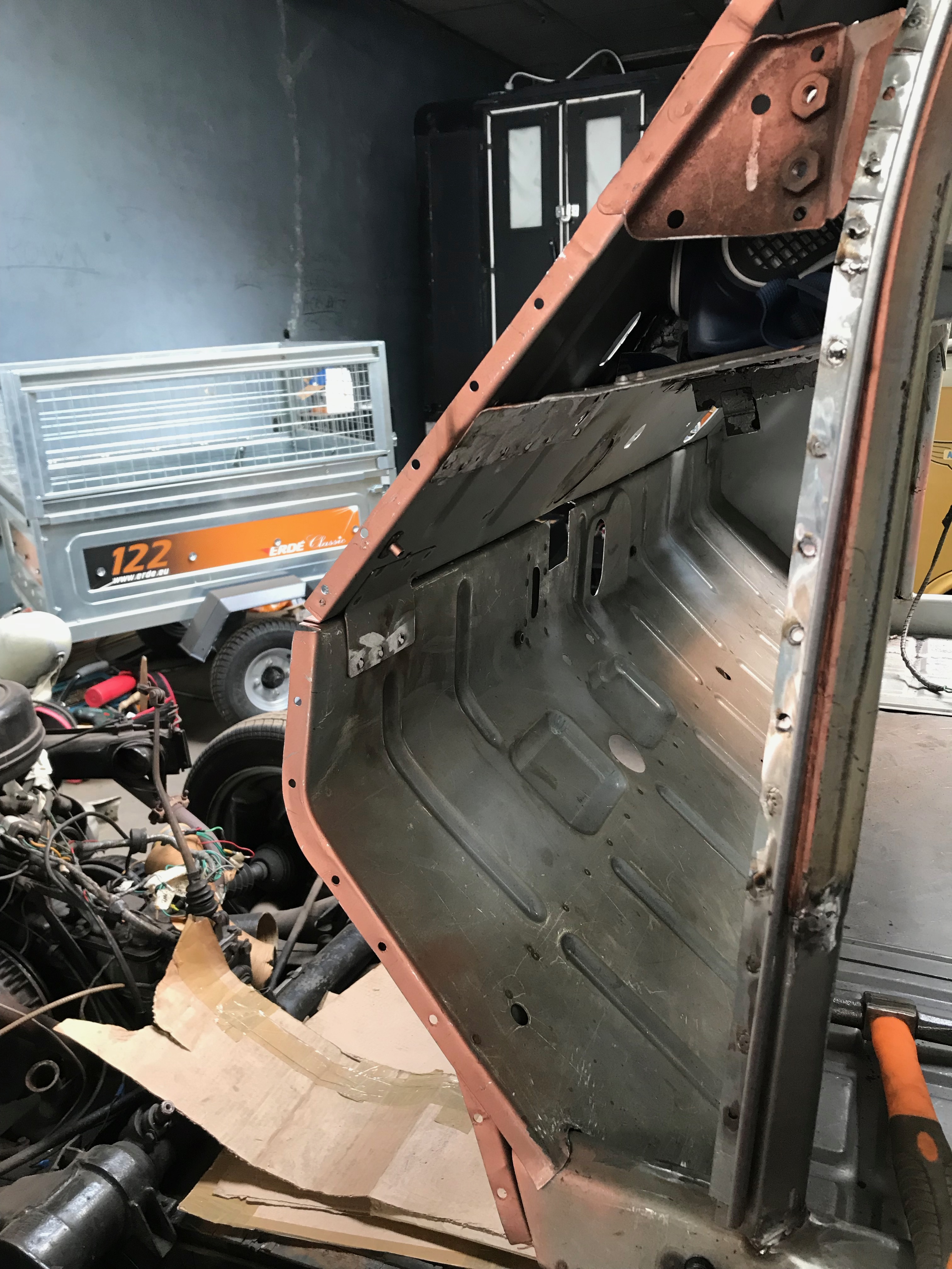
Lastly, I dressed the join where the sill slots into the toe board and have seam welded it. This was tricky to weld and turned out a bit ‘blobby’ where I attempted to run a nice fillet along the join. There’s a big gap here, it would not have welded very well ‘as’ is’

After a bit of bashing with the hammer and the join is nice closed up

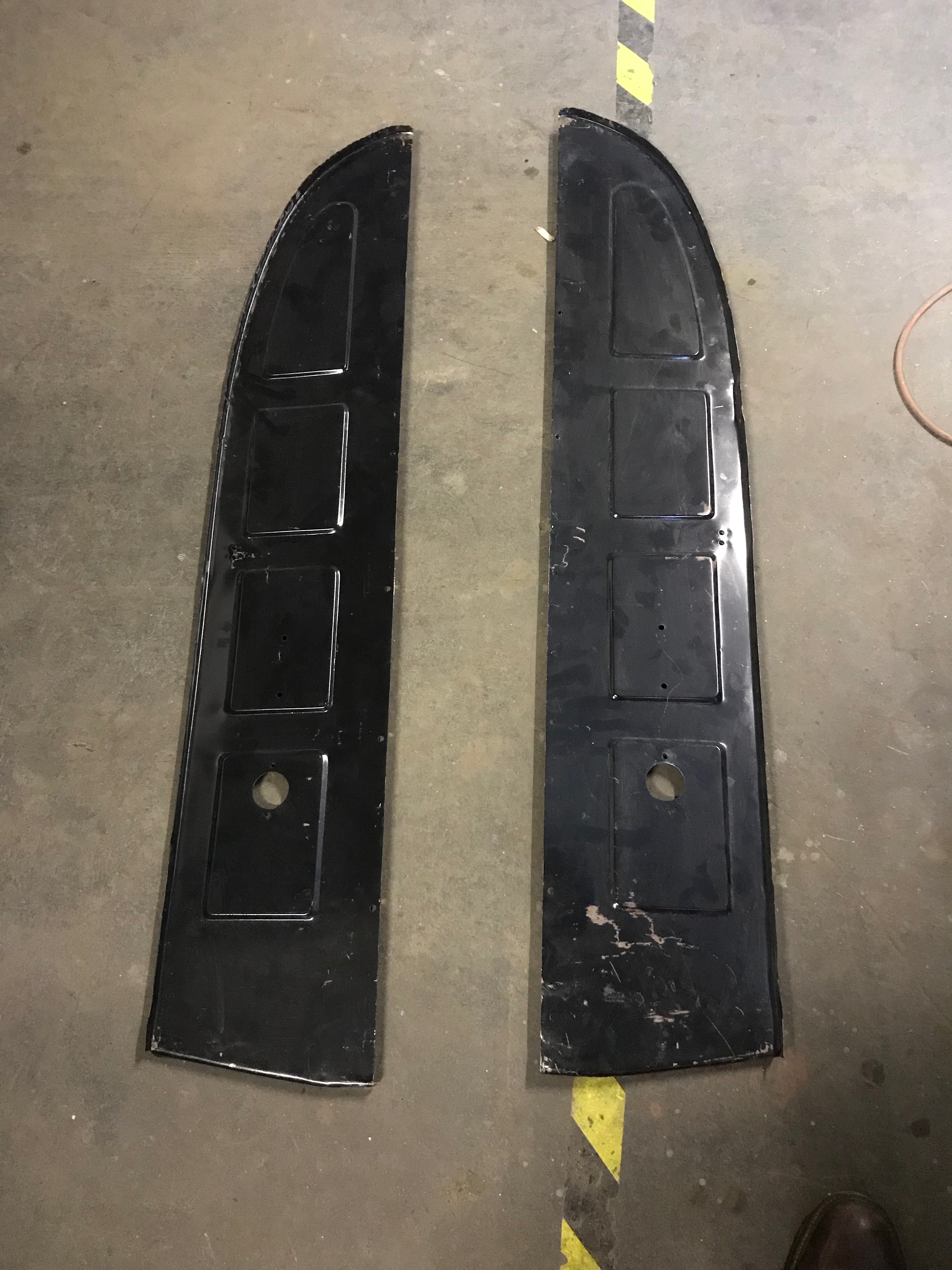
Here are the 2 old A post sections, complete with hinge mounts.

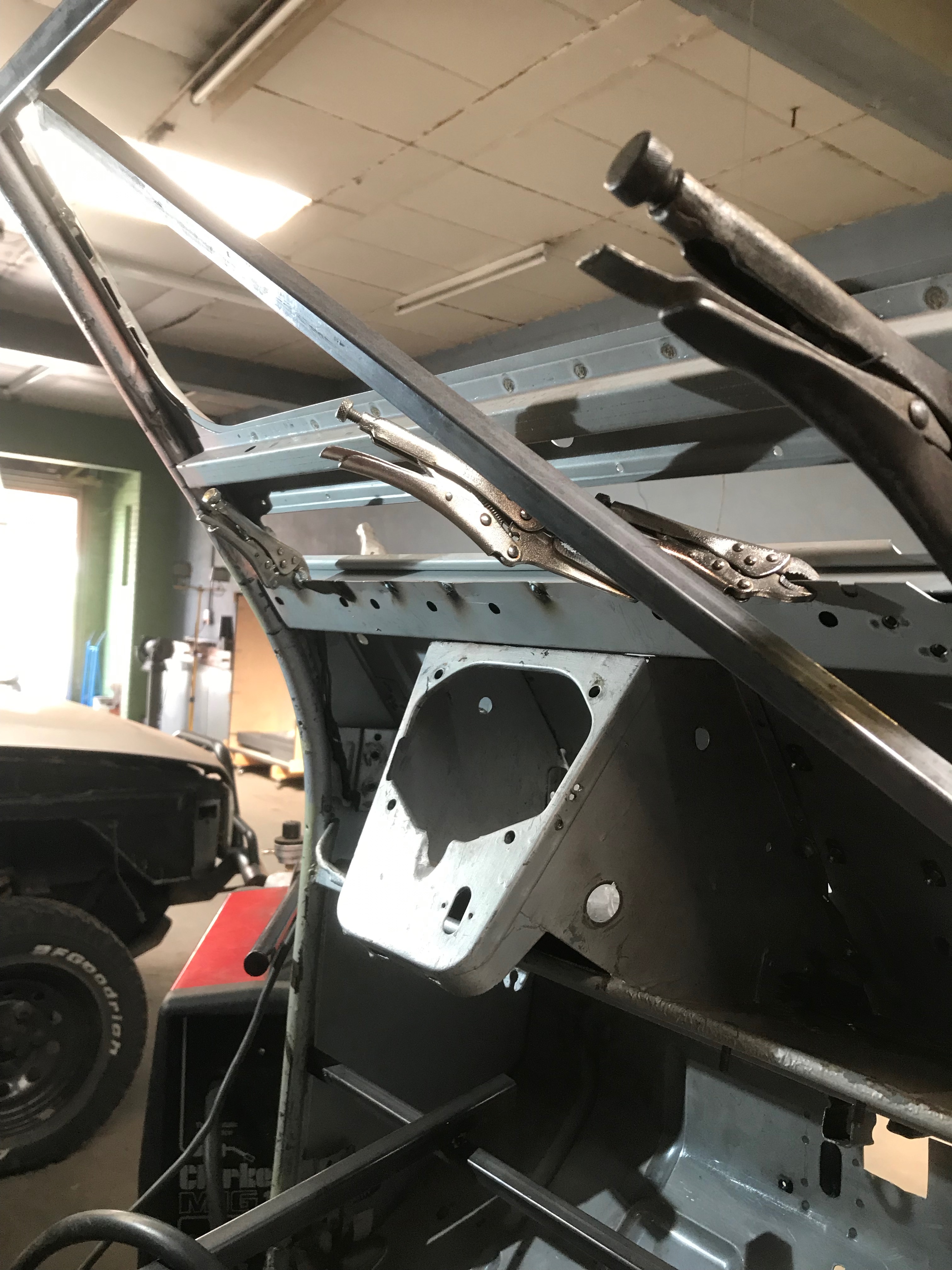
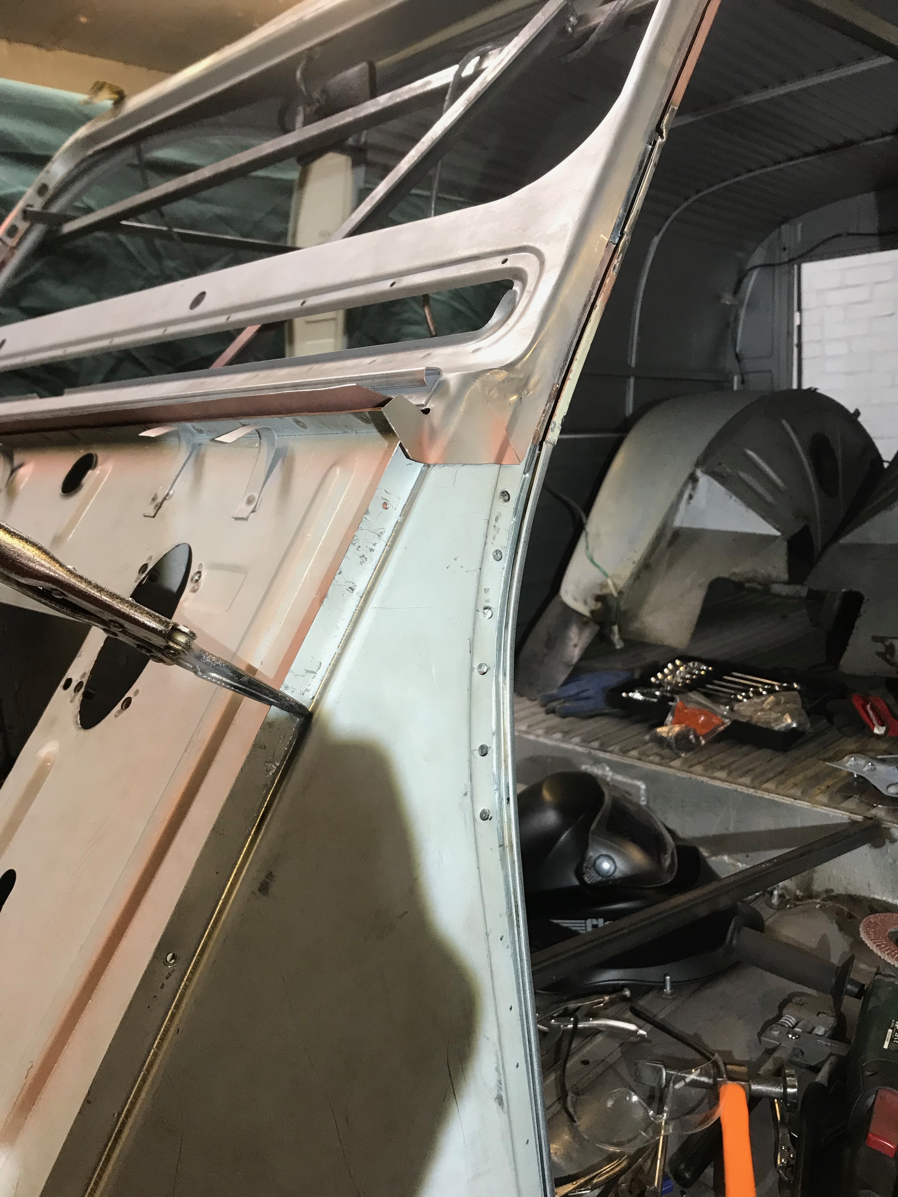
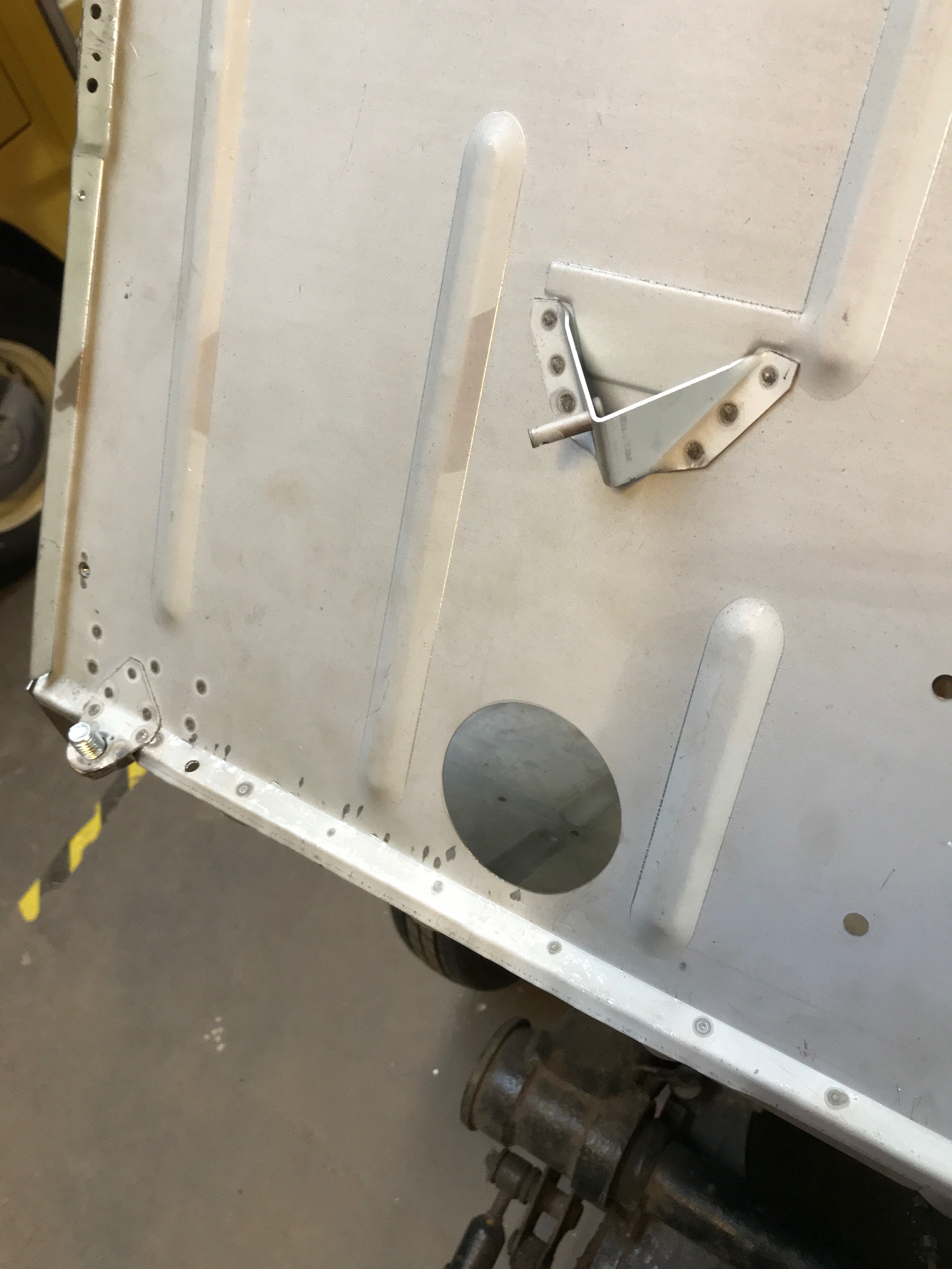
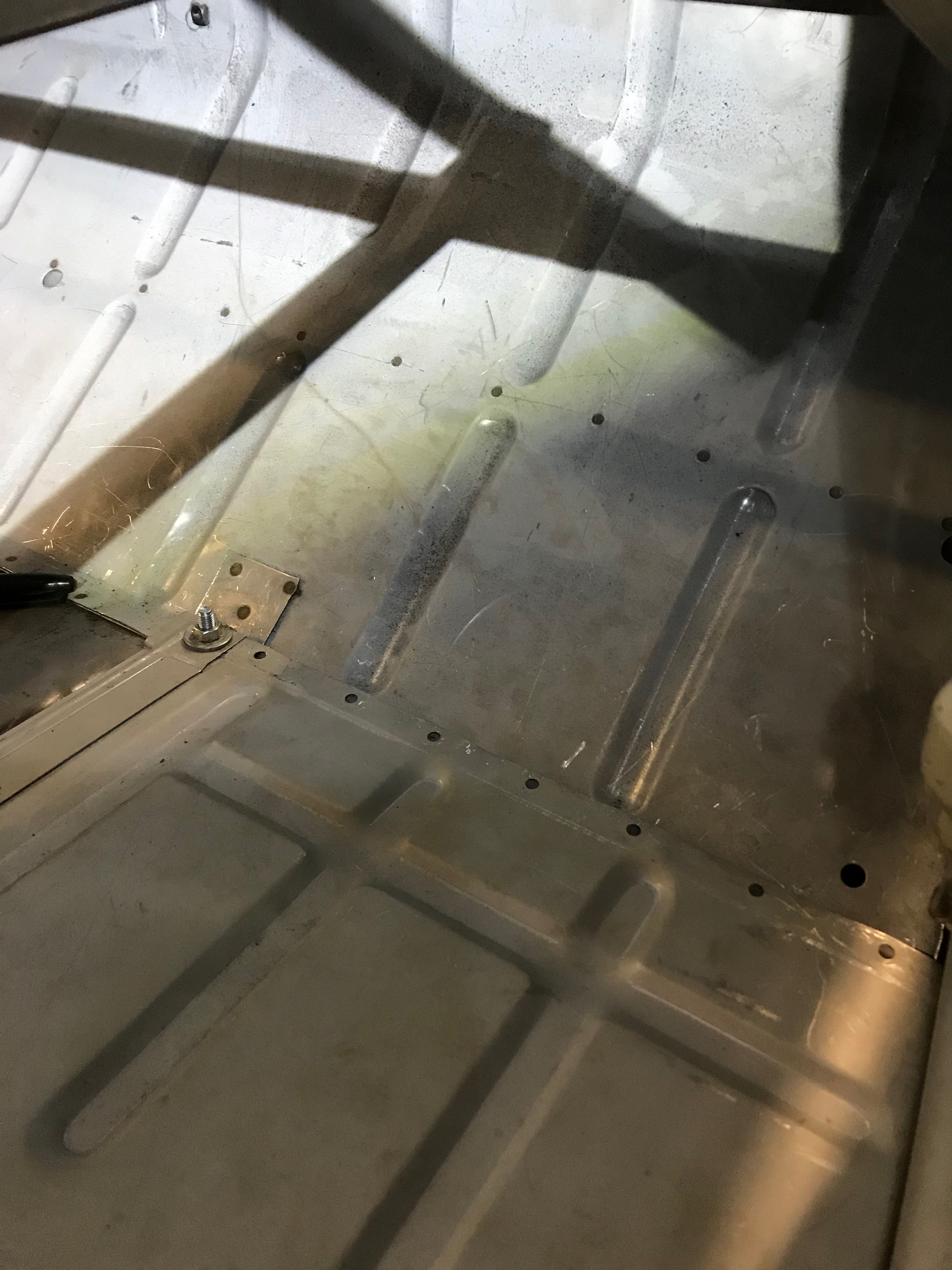
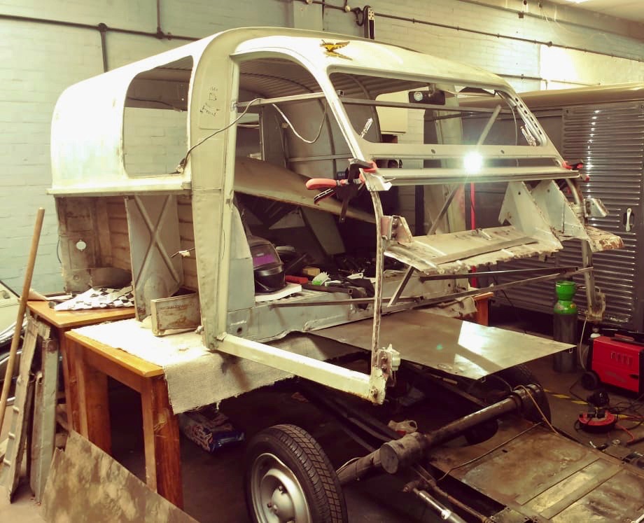
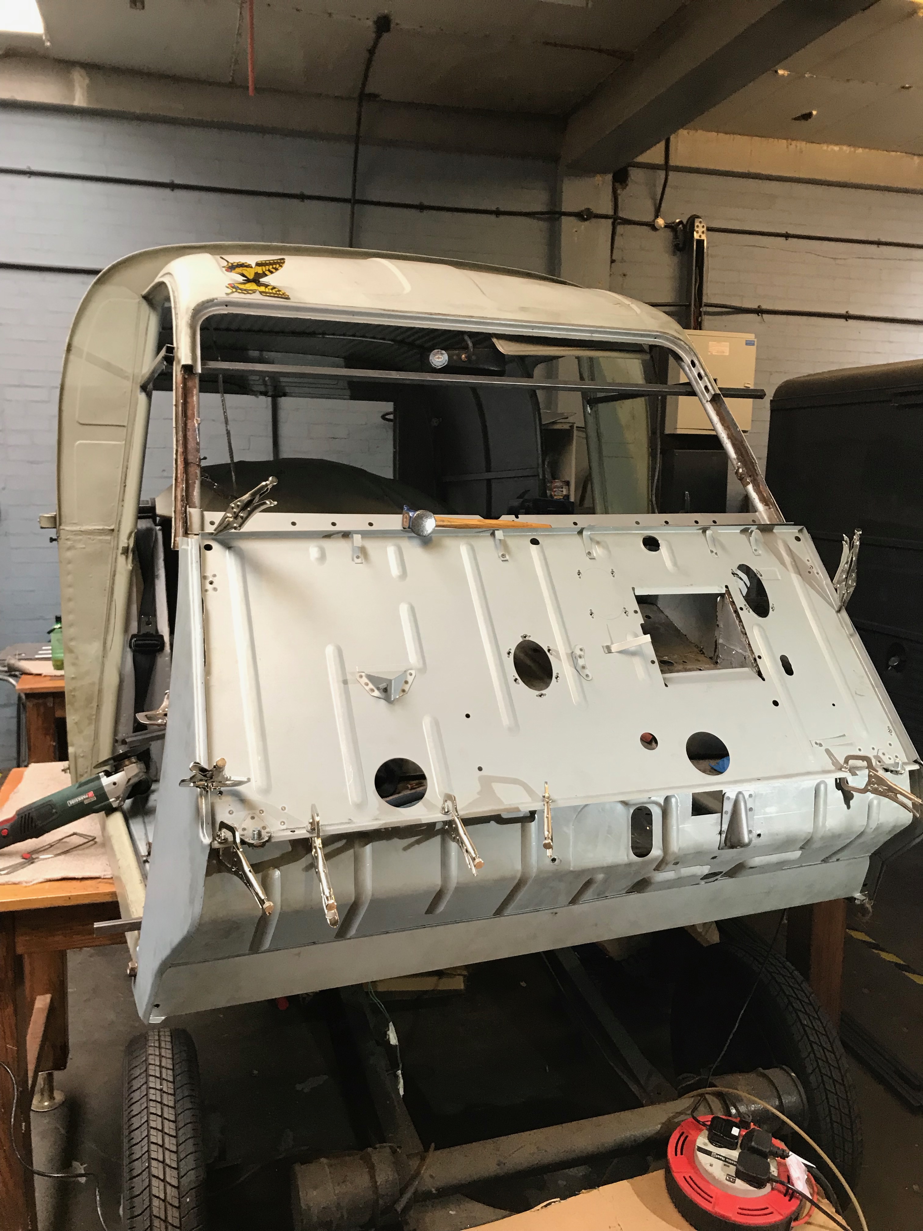
Flushed with success, I did the same on the nearside, although I haven’t welded the A panel in yet as I ran out of gas (or I might have forgotten to turn it off) . You can see below all the holes are ready for plug welding. This all went relatively easily – especially after the nightmare of the windscreen. Next jobs – fit the bottom hinge brackets and see if the doors still fit (I’m sure they won’t), join the top of the firewall to the bonnet hinge flange, and check to see if the windscreen will still fit in its new aperture. I’m less worried about the screen fitting than everyone else is, because my son works for a glass company and he said he can make me a new laminated screen to my measurements if needed..

Screen 2 – the sequel

I’ll start this blog with a quote from ECAS (parts suppler for all things Citroen 2CV) regarding the windscreen repair panel.

Please note: This panel is not easy to fit and might require the attention of an expert car body specialist.’

I’m no expert car body specialist and having made a pigs ear of fitting one of these first time round, I have to agree that easy, it is not. It took me most of a day of fiddling around to get it into the right position in order to weld it into place. The most challenging part is aligning it with the A panels, which I have not properly fitted yet – and can’t do so, until the bottom of the A posts have been repaired and the sills are fixed in place. Trying to stretch and bend a recalcitrant second rate steel pressing around a framework of loose and equally floppy bits of metal is enough to try anyones patience and being the type of person that likes to adopt his approach on the fly does not help matters. I could have drawn up a Gannt chart and plotted the critical path for this project, and then nothing would have been done out of order, there would be no known unknowns but that would have been dull and I would not be writing this blog and you would not be reading it. Still, as you are reading it out of interest or if you want to replace your own 2CV windscreen surround with a pattern part pressing then read on.

I fixed the sides of the panel to the existing frame first with 3 puddle welds each side and then seam welded the join between the edge of the old frame and the new. This went reasonably well, except that the new panel doesn’t have the same depth of the old. There’s a bit of a gap which I will have to seal up, either with mastic, solder (lead loading) or braze. I’ll have to try solder and brazing first and if I make a fist of it, run a bead of mastic over the join.

All clamped up – bit of a gap here but there’s new steel under the join so I can run a bead of weld over this without blowing through and grind it flat
You can see here where the pattern part is creased where it’s been formed around the tooling. It looks worse than it is – I spent a bit of time re-forming it with a hammer and dolly, so with a skim of filler or lead it will look fine when painted

Back to the other side, I drilled, rather than punched 3 holes to puddle weld it to the door frame

Welded and ground flat – still needs a bit more finishing off, but its well and truly fixed to the frame

Having secured the sides, I set about welding the lower side of the vent flap opening from the inside to the windscreen panel. Lots of puddle welds, which all went fine. I ground them flat, even though they will not be visible once the dash panel is in place..

Plug welded all the way along the lower cross member

Welding the screen panel to the upper cross member was a whole new world of pain. There’s no room to get the hole punch into the screen frame, besides I wanted to weld it from the inside so that the screen rubber would fit properly. In the end, I turned the welder down to minimum and ran bead of weld along the edge of the seam where the 2 panels meet. It took ages as I had to stitch it together a few inches at a time and then grind back the excess (aka huge blobs of weld) along the edge. By the time I was done, I’d become tired and emotional and just wanted to wrap up fo the day. I’ll finish grinding the edge back next time I go to the workshop and will post a picture. I’m not sure what the recommended method is for this last bit of fixing is – probably to use a proper bodyshop spot welder, but I think I’ve managed to sort it the hard way.

To finish off the job, I’ll need to join the new panel to the upper lip of the firewall – I think this will have to be another seam welding job, as I forgot to punch any holes in the bulkhead flange before I welded all the other edges and now I can’t get the tool anywhere near it to make the necessary holes for puddle welding. Another job that would have been on the critical path.

So yes, it was tricky but not impossible. I wonder how much I’d have to pay a body shop just to fit this one part – and how they would go about it.

Next job is to replace the bottoms of the A posts, weld on the hinge brackets to the sills and trial fit the doors again. I have a feeling that the doors are going to be my nemesis – even before I started they appeared to be too big for the door frames…

All in all, not a bad day. I’m going to finish off by having a quick rant about the Citroen 2CV club. (2CVGB) I joined the club seven years ago so that I could go to the world meeting in Oxford in my newly acquired van. I ‘unjoined’ when I found out afterwards that I was charged the same entrance fee to the meeting as a non member which I though was a bit rich and not really in in the spirit of things. However, 6 years later, I thought I’d give them another go – really this is so that I can get onto the forums. The 2CVGB must be the only car club in the UK that sets membership as a prerequisite for partaking in what would otherwise be a public forum. No matter, It’s under £30 for a yearly membership so is not gong to break the bank. Anyway, my membership details arrived yesterday and as instructed, I went on to the forum site to get registered. It failed. ‘Your email address has already been registered with this site’ was the pithy message that was displayed. Brilliant, I thought – I just need to reset my password then. Nope, I can’t do that because I’m not registered according to the next helpful error message. I work in IT and this sort of nonsense really gets my goat. I’d be more than happy to help the admin sort this out, but I have no way of communicating with them without access to the forums…

Gutter talk

On the list of things to do from the previous blog was to sort out the gutter (drip channel) – the tiny ‘U’ shaped bit of metal that runs along the side of the roof down to the nut that secures the back of the front wings to the body. These often rot away down the A posts and as such are missing from many 2CV’s and have long since disappeared from my van. As I’m replacing all of the structures around the drip channels it would be remiss of me not to re-instate them. Armed with a new length of drip channel, a pair of tin snips, hole punch and the welder, I stood back and wondered how on earth I would be able to bend a curve into a thin strip of metal folded into a right angle without kinking or creasing it and keeping it flat to the A post whilst fixing it into place.

The other problem was that since these were missing originally – and as I had already detached the old A panels from the A posts, there was no clue left as to whether the channels should fit under the A panels or over the top of them. Half an hour of looking at, trial fitting, standing back and generally being unconvinced either way left me (and Pete) at an impasse. I sent a text to Tony at Le Garagiste in Ipswich (THE 2CV guru), asking for guidance and added a thumb’s up, smiley face and a Munch ‘scream’ emoticon to the text and awaited a reply. ‘Your text has been forwarded to a landline number’ was the only response I got. I idly wondered how the emoticons would be translated from text message to the spoken word – in particular ‘The Scream’ and then realised that I would never get a reply from Tony and even if I did, it would make no sense at all. It was Sunday and I didn’t want to ring him to explain so left it at that. By this time, Between us, Pete and I figured it out. Drip channel first, then A panel.

Here’s a picture where you can see the drip channel ending abruptly, level with the end of where the old A panel was (just above the copper coloured primer)

Sans channel de douche

Having agreed that the drip channel must fit under the A panel we then set about making it fit around the curve of the A post. I’ve seen curves put into wheel arch flanges by using a stretcher / shrinker tool. I was going to buy one of these and have been waiting for a second hand set to appear on eBay or Gumtree for at least 5 years, but have had no luck.

Here’s what you can do with a stretcher shrinker

metal curley wurleys

I might as well run on about stretcher shrinkers for a bit – they are a brilliant tool, but the cost can be prohibitive – here’s why. You can buy one stretcher/shrinker hand operated machine for about £150 – £200. It comes with 2 jaws, one to stretch and one to shrink, so unless you want to spend most of your time swapping the jaws over when you are making compound pieces (like the one on the right above) then you’ll need to buy 2 machines (another £200). Then you’ll quickly realise that you can’t make it work properly and hold the steel at the same time (you only have 2 hands, right?), so you’ll need to buy a foot operated model (another £200) so before you know it you’ve spent £600 on just one tool..

”How do they work’ I hear you ask… They are like a horizontally mounted vice with jaws which are about 2 inches wide and half an inch deep. One set has teeth cut into both jaws which oppose each other facing inwards from the outside edge – this is the shrinker. As the jaws are clamped onto the steel, the teeth force the steel together, thereby shrinking it. If you shrink half a strip of steel it will put a curve in it. The stretchers teeth are oriented the opposite way and therefore have the opposite effect. Using both tools on a piece of steel pre-folded at right angles will enable the piece on the right above to easily be fabricated since it is made by stretching on one plane and shrinking on another.

Anyway, I don’t have one of these wonder tools so have to make do with a more pragmatic approach which was to cut a series of slots in the channel and bend it around the A post a section at a time, welding, bending, welding, bending and so on

‘Bending the drip channel to match the curvature of the A panel

After the gutters had been formed around the bend in the A Post, we (Pete and I) offered up the A panels, so see how they fitted. All is looking good with the ‘cut and shut’ job on the gutters hidden out of sight.

more holes will be punched into the A panel before plug welding. This picture also shows the ‘bruising’ on the corner of the screen repair panel where it fits over the top of the A panel – caused by the dodgy tooling used by the manufacturer

I won’t do any more with the gutters until I’ve chopped off the bottom of the A posts and made good the join between the A posts and sills.

I started work on fitting the windscreen repair panel to the front. This repair panel is not made very precisely and to be brutally honest, does not fit very well at all. The caps which fit over the top of the A panels are not very well formed (see above picture) and the channels which run up the front of the A posts don’t close around them as they should. In an attempt to resolve this, I added a small strip of steel to the A posts – (see below), so that I’d have something to clamp and puddle weld to. It’s still not a good fit and after I’d punched some holes in it, bent it about even more and generally ruined it, I gave up and decided to swap it out for a new panel. It turns out that the best fitting panel is the one made using the original Citroen tooling. At £300, this is not an option – I just don’t have the budget for it. – Apparently the manufacturers do not want to wear out their nice tooling by making repair panels at a lower profit margin and they would prefer to make more money by selling the complete fabrication. I’m happy to scrap the old panel and try again with a new one, but it is irritating nonetheless. I am minded to write a letter to Parts Industries to see what they have to say, but I’m not expecting much as they are a Dutch company and as sure as eggs are eggs, will be typically empirical in their response – ‘if you want a good fit, then you have to buy the more expensive part…’ is what I expect they will say – in true Dutch style. An example of this is when my sister in law went in to a cheese shop in Amsterdam and asked them if they had some Edam for sale. The response from the assistant was: ‘Well, you are in a cheese shop and this is Amsterdam, so of course we have Edam….’

Here’s the small fillet of steel I put in to make up for the badly made screen repair panel. I have since plug welded it the door frame flange, but the screen repair will not butt up tight to the new steel, so I won’t be able to get a good weld to it. Note: the small ‘U’ shaped bit of new steel which will enable me to make a good repair between the old and new parts

Anyway – that’s enough moaning from me. I’ll have another go at it when I get the replacement screen repair panel.

In other news the rear bumpers have arrived from France. I’m looking forward to sorting these out and will be fitting them later.

Brave new weld

Time to take stock again and look at what order I should complete the tasks on the cab. I think this is what to do next

Peen (what a lovely word…) over the front edge of the firewall where it joins the toe board

Fix the front of the sills to the toe board slots

Weld the inner screen cross-members to the outer screen panel

Replace the bottom of both A posts

Fix the new bottom hinge plates to the A posts

Weld on the A panels

Peen the front edge of the A panels over the sides of the toe board. mmm…peen..

Shape (cut, bend and weld) and then fit the gutter repair section to both sides of the van

Weld in the outer screen panel

That’s a fair bit of work, so I’ll tackle each job at a time, so the next few blogs will document how it all goes

The body work at the cab end of the van will then be finished – except for a bit of tidying up on some of the welds and zipping up the floors to the sills, which will be easier when I turn the body onto its side (or roof). I need to clean and repaint the inner rear wings before the outer panels can go back on, but prior to that I’ve decided to have another look at the ‘new’ rear door pillar panels I bought a while ago – to see how much effort it would be to fit them. Here’s a picture of them

A bit scratched and a few small dents, which I can planish out

and here’s what they will replace if I choose to accept the ‘mission’ of chopping out the old and welding in the new. The old panels have had a bit of bashing in the past – I can get behind them with a dolly, but it’s difficult to re-shape such thin metal when it’s been stretched – it just wants to ‘pop’ back to its damaged state. I think this is known as the ‘oil can’ effect.

It’s all a bit wrinkly – the bottom right corner was bashed in when I reversed into a bollard, I did manage to pull some of it out but it’s still a mess

On the face of it, replacing the panels is a reasonably straightforward job. There are a load of spot welds to be unpicked and I’ll have to carefully separate the top and bottom panels on each side. I now know enough to realise that the top gutter part will fall apart when I try and remove it, so I’ll need to buy a replacement for this. What worries me a bit is what sort of edge will be left when I detach them

Where the bottom valence has been replaced in the past, the lower box section will have to be separated. The lower section of both back panels have also been replaced in the past, but the rear bumper is long gone. The rear valence should have 4? holes in it to accept the tubular bumper, which I guess is welded to the inner part of the box section. I’ve spent ages trying to get a replacement bumper, but they are not being manufactured any more and second hand ones are like hens teeth. However, I have managed to track down a pair of AK250 bumpers – in France (thanks to Mark Griffin for sorting this out) and since I have no pre-made holes to work around the fact that they are two as opposed to one bumper is neither here or there

They will need a bit of cleaning and I’ll have to devise a method of fixing them to the rear valence as the replacement panel or repair which was fitted during the last restoration did not have any holes in it.

Bruised!

I’ve also cut out a small section of the firewall so that the brake master cylinder mount can be bolted flush to the bodywork. I had to use the old chopped out bulkhead for reference which has been dragged about and handled many times. I’ve grown quite fond of it and might turn it into a piece of wall art when I’m finished, perhaps the Tate Modern will want it installed in the Turbine Hall. I also noticed that I have a hole missing in the new bulkhead and a spare ‘oval’ hole in the wrong place. I can make a nice plate to go over the spare hole and I’ll have to cut out the new hole with a hole saw. I know I have a set of hole saws somewhere, if only I knew where they were….

x marks the spot where I need to cut a new round hole. The oval hole on the right of the battery box will have to be blanked off – I think this part of the screen demising setup for later cars

When I find the hole saw set (or buy another) I really could do with cutting another hole in the bulkhead and installing a heater tube on the drivers side footwell to keep my toes warm in the winter, so I suppose now is the time to make this modification. All this hole cutting will leave me with 2 spare discs of steel, which I might be able to use to fill in the indicator holes in the front wings – more on this later.

Putting a braze face on it

There are plenty more puns waiting to be aired so you’ll just have to put up with them. On Sunday, I spent a whole day in the workshop and got stuck into welding up the front of the van – The firewall is in and attached to the toe board at the bottom and the lower of the inner windscreen reinforcing panels – (the one that the wiper motor is bolted onto) is fixed to the A posts. It’s taken a lot of fiddling around with the outer screen repair panel to get the reinforcing parts in the right place. My biggest concern is that the windscreen aperture won’t be the right size for the glass so I measured it more times than I care to remember – each time I got a slightly different result, so until the rest of the panels under it are fixed, it will have to do..

Starting with the firewall – the picture below is looking up to where the toe board joins onto the firewall. This is the join you can see which is under the battery box and runs in between the bolts that hold the wings in place. I punched a series of holes in the toe board flange and plug welded them from underneath

Looking up where the toe board joins onto the firewall.

Below – looking down at the join between the firewall and the toe board – the plug welds are on the underside of the lip, but you can see the hot spots where the plug welds have penetrated the steel, which means they a good welds.

firewall to toes board join

The next task was to fit the windscreen cross member. This runs in between the A posts and is hidden by the outer windscreen repair panel. The old one was brazed at the join here, but I have plug welded it in place on both sides as I don’t have any brazing skills yet. I’ve tidied up the welds since this picture was taken

a few spot/plug welds to fix the windscreen cross member in place

To finish off the firewall welding, I joined the top hinge mounts to the inner edge of the firewall with 3 plug welds and ground them down flat. The A panel will fully encapsulate the mounts, when they are fitted later and here’s a picture of one of the tabs which re-inforce the joint between the upper toe board edge to the lower firewall edge. I had to break out the long grips so that I could clamp the tab to the toe board ready for welding

nb – the pink hue is weld-through primer which I’ve sprayed onto the flanges before welding

I think I’ll leave the outer windscreen panel until last. There are some awkward bits to sort out, not least the 2 parts where I’ll need to join the repair panel to the existing shell. Before I can do this, I’ll need to cut and bend the gutter repair strip, which also needs to be put in place before the windscreen outer but after the A panels are in place. The A panels can’t be fitted until I’ve fixed the grotty mess of rust at the bottom of the A posts and welded in the new bottom hinge supports, so I guess this is the next job – oh, hang on, I need to fix the sills where they slot into the toe board first . This is a brazing job which will be the first bit of brazing I’ve done since being at school.

As for brazing, it’s just one of the methods for joining mild steel. The MOT testers won’t pass a car that has been brazed together as opposed to welding, but a combination of the 2 methods is acceptable – especially when the braze is used to seal the joins between welded panels. There are a number of methods for brazing, all need a source of heat to melt the brazing rod and at the same time, get the metal hot enough to allow the brass to melt and flow into the joint. You also need flux, which allows the molten brass rod to flow evenly by capillary action in between the two bits of steel which are the object of the task. Some rods come ready coated with flux, however my understanding is that flux also needs to be applied between the 2 sheets of steel… Pete and I had a play around using the ‘arc’ method, where a tool is used to bring 2 electrodes together until an arc is created between the electodes and backing them off slightly to maintain a crackling blue orb of intense heat around the ends of the electrodes. One has to then move this plasma like ball of energy close enough to the steel to heat it up and introduce the brazing rod, spreading the braze around the joint in the hope that it will flow into the gaps. Our experiments were spectacular in that a great deal of concentrated energy was produced, the rod melted and so did the steel that we were trying to braze. ‘I haven’t done this for a while’ declared Pete. I stood back in awe as the crackles and sparks ensued. ‘The rods are a bit old, I think they are coated in flux, but I reckon we need some flux on the steel as well’ shouted Pete as the test piece he was working on glowed cherry red with bubbles of molten goldenness rollong around the surface of it. Despite this, there were indications that this method could be made to work.

The alternative is to use a flame to generate the required heat (ie blowtorch) – or lastly we could use the TIG welder with some brazing rods. More on this later – or I might break out a tube of seam sealer and make do with that.

In other news, I’ve discovered that I’ve been using 0.8ml MIG wire instead of 0.6ml wire. 0.6ml would be much more forgiving than 0.8ml on such thin metal used on the 2CV so I’ve either been very lucky to get away with using the thicker wire (which produces more current and greater risk of burning through the metal), or my MIG welder is capable of compensating between the parameters of the two voltage settings, wire speed and diameter in its stride OR my welding skills have improved so much that I am able to do it by instinct alone. I think I’ll assume the welder has become self aware and it is making up for my errors and mistakes.

Welding has started

Actually committing to start welding is quite hard for me. I’m always worried that I’ll do something wrong and make an irrevocable mistake which I won’t discover until it’s too late to do anything about it. Also working on one’s own can be a barrier to actually doing anything at all. My pal Pete has been good at egging me on, so thanks to him, I have made good progress this weekend. I’ll repay the favour at Thursday nights ‘old mans memory club’ with a few beers. Pete also brought along a spot welder to the workshop. It’s a bit crude but it is effective. Basically, It’s a carbon rod on a spring loaded handle that you use to strike an arc and then release a few millimetres to keep the arc going for a few seconds. During these few seconds the metal beneath melts and fuses together – or melts and makes a nice red hot hole if you are not careful. It has 2 settings, so with a bit of practice, I’m sure I’ll find the optimum combination of amperage, timing and arc length. More on this in later posts.

I’ve fitted the sill and floor to the nearside and plug welded it to the lip at the rear of the floor and at the front where it sits on the toe board. Everything is lined up nicely, so the next job is to repeat the process on the offside.

I chopped the old sill out and unpicked the welds where the B Post saddle fits onto the sill. I will be replacing the bottom of the A Post and the hinge plate, so I just sliced through this bit at the front of the van with the angle grinder and 1mm disc.

This is the old nearside A post, just tacked the hinge onto the sill temporarily until I repair the A post and replace the hinge mount
This is the offside B Post. It was a bit crusty at the back of the sill, so I made a little plate to tidy it up – the holes are ready to be plug welded.

Before I welded the floor and sill, I punched a set of holes in the front, rear and side of the floor (where it butts up to the sill). A couple of holes in the B post saddle will enable me to plug weld the sill to it.

Here’s the front and rear of the floor bolted to the chassis jig, with its set of punched holes, ready to be plug welded

I’ll weld the back of the floor in place and then fit the sill.

Here you can see how the sills slot into the toe board. I’ll clamp the small flange to the side of the sill and use Pete’s spot welder to make the join good. I reckon this will make a neater fix than trying to grind down a seam or plug weld in such a confined space . After that I’ll replace the bottom hinge plate. Note the inside of the A panel with the sticker on it. This will be folded over the toe board to close the gap. I’ll spot weld it first.

The sill fits neatly onto the slot in the toe board. My plug welds are a little agricultural, so I’ll grind them back a bit with a flap disk and tidy them up before I paint

If you are reading this and have a 2CV, keep a close eye on these inside corners at the front of the car. The ribbed rubber mat normally sits over these joins and you won’t spot the rust taking hold until it’s well established. If you are looking to buy a 2CV, have a good poke about in this area with a sharp pointy tool (screwdriver) if you can. If the owner is looking over your shoulder, then press hard with your fingers and listen for any crunching noises and watch for any ‘give’ in the panels. The 2CV is made out of very thin panels but it all makes for a very strong structure when it’s all nice and new and properly zipped up.

Rust, Cheese and Ketchup


The front parcel shelf has been bothering me for a while, not least because its so rusty but that it hardly functions as a parcel shelf at all.    It’s not level for a start and its cheese shaped, so anything that looks like it should fit into it, doesn’t –  unless it is a piece of cheese and has been put in place thin end first.   I like cheese as much as the next person, but as I have a van, I don’t need to store cheese on my parcel shelf – I can just throw it in the back.

Parcel shelves are a black hole for small things.  Any loose change disappears when put on it as the coins slide towards the front and become wedged in the join between it and the firewall.  Pens roll to the back and there’s no way that they can be got at using just fingers.  Among the list of things I removed from the parcel shelf before I started the project are:

Some boiled sweets which had bonded themselves to the innermost edge at the front and had to be chipped out with a screwdriver

A selection of nuts, bolts and washers that had become detached from the van at some point but had no obvious home or source and no discernible detrimental effect on the looks or performance of the van.  However, like the loose, used fuses one keeps in the kitchen drawer (some of which have blown) and perished elastic bands that might come in handy one day,  can never be thrown out and are destined to accumulate

A McDonalds Hash Brown – AKA a ‘greasy slice’.  These do not decompose and some 5 year old sachets of ketchup with a use by date that’s long expired but nonetheless will taste the same as the day it was made

A fuel loyalty card.  Which will never accumulate enough points on it to buy anything because a 2cv uses so little petrol

Its just like the back of a sofa but with less gritty bits – what are those gritty bits and where do they come from?  Another one of life’s less interesting mysteries that doesn’t warrant delving into.

Anyway, back to the parcel shelf – it does add some structural integrity to the front of the 2CV and therefore must be sound. Mine isn’t.  Removing the firewall has pretty much destroyed the front edge and what’s left is too rusty and thin to be able to weld back on to the firewall.  I could buy a new parcel shelf but that would involve removing the instrument binnacle, which would leave that equally compromised.. and it’s another £80, which I’d rather spend on beer.

Here you can see where I have cut the front two inches off. 

I made a repair section out of 1mm steel, put a fold into the front edge of about 120 degrees and used my joddler tool to punch a set of holes along the front edge (for welding to the firewall later) and a set of holes so that I can plug weld it to the parcel shelf


I could only puddle weld a couple of holes at a time, because it was difficult to clamp the 2 sheets together – anyway I managed to zip it up all the way along, including 4 welds to attach the new lip to the handbrake ratchet.  Here’s a picture of it with the welds ground down.  It’s not a perfect repair but it is strong and nobody will see it.

While I had the welder and cutting gear out, I decided to repair this rusty bit of the upper A post. This is where the windscreen re-enforcement panel is brazed and as you can see, has all but rotted through.

I cut out a section of the A post and cut a bit off the A post repair section that I got from ECAS and stitched it in carefully by using the welder to first tack it in place and then to join up the dots.

My next job will be to replace the gutter section that runs from the back of the cab to the bottom of the A post.  My gutters finish abruptly at the top of the A panel, I think they had just rusted away and were  clinging on with the very weakest of joins with the A post – so when the last restoration was undertaken, they had to go and were never replaced. 

I’m not sure how I’m going to bend the new gutter to fit the profile of the A post without a stretcher / shrinker machine  – and even then I think it would be a struggle.  I’ll probably have to cut a series of slots in it, bend it to the shape I want and then stitch it back together with the welder.  Something for a future blog I think. I can’t figure out whether the gutter is fitted before or after the A panel. I think after would be best and I also think it is brazed rather than welded. I’ll need to learn how to braze or try and remember what I learnt at school in Metalwork, when we made pokers with brazed handles. Mind you, then we had a forge at school and were unfettered by health and safety nonsense. None of us wore overalls or safety glasses. If you burnt a hole in your eye, you must have been too close to the inferno and would have had a detention given to you for being stupid. Imagine a class of 15 year old boys waving rods of cherry red hot metal about in each others faces, while the teacher re-lit his pipe with the forge’s gas lighter, oblivious to the mayhem around him…

Footnote

Toby was in the workshop today, welding patches to the body of his VW LT35 Camper – all was going ok until he tried to weld a patch over a hole which was lined with wood and insulation on the inside.  Yes, it did catch fire, but was quickly put out.  I expect Toby will remove the interior before he welds any more of the body… (this is the same as changing into old clothes in order to paint your house but only after you have started and got paint on your best clothes )

Let’s get Jiggy with it

I have to admit that I’ve done another U-turn. In earlier posts I wrote about making a jig for the chassis. A jig is a fabricated frame which matches the chassis dimensions upon which the body can be mounted temporarily whilst being worked on. The idea is that when it comes to putting the finished body back onto the chassis, everything will line up nicely – the jig acting as a template.

The book of ‘How to restore a Citroen 2CV’ states categorically that the body must be bolted back onto the chassis before fitting the new floor panels, sills and toe board. For me, this would involve putting the body back onto the chassis and then having to crawl around on the floor to weld, raise the whole van somehow to get underneath it, or go through several iterations of body on – tack weld, body off – seam weld, body on – check, body off – finish welding.

I rejected the jig idea as I thought it would be too difficult to make a perfect copy of the 2CV platform chassis but after having talked it through at the old mans memory club, I decided to give it a go. I’d have nothing to lose, because if it turned out to be a bad copy, I could write it off and will have just wasted more time and materials.

Firstly I cut a sheet of steel to match the width of the upper side of the chassis. Then I used one of the captive nut clips, to mark off where each of the holes would need to be drilled to match those on the chassis. It would have been easier to have used a roll of paper to make a template – ie lay paper over chassis, poke holes in it where the bolt fixings are, transfer paper to steel sheet, cut and drill. I didn’t have a large enough sheet of paper and there are no shops near the workshop. Besides, I was on a roll (no pun intended) so I carried on anyway. With the holes drilled on one edge of the sheet of steel, I bolted it down (approx 8 bolts per side) and then drilled the other side. I now had a long floppy tongue shaped sheet of metal with all the holes in the right places, which matched those on the chassis. I welded a frame of box section to the underside of the ‘tongue’ so that it would remain rigid when bolted to the body. Here’s a picture of it in place.

The Jig fitted to the body – if you zoom in you can see both rails welded to the underside of the tongue and the holes drilled on each edge where the new floors will bolt on to it

With a bit of lifting the two Pete’s and I slid the jig under the body and bolted it to the body. We only had 2 bolts each side, but they fitted perfectly, so between us we agreed that the rest of the holes and their alignment must be correct.

A trial fit of the new panels, including the sill confirmed that this was the case. Somewhat worrying was that the distance between the centre of the bolt which sticks out of the sill, to the back of the body was 12mm different on each side. As I am replacing pretty much everything which makes up the van cab, Pete and I concluded that it was wise to use the same measurements for each side for the sills and with everything clamped into place, that this distance would be dictated by the pre-drilled holes in the new A-panels, we settled on cutting the new sills to the same length each side – using this a datum to fit the rest of the cab around them.

Yours truly. Here all the panels have been clamped into place and aligned to the floors and toe board, which have been bolted onto the jig.

Clamping on the rest of the new panels has given me a new problem to solve. The new sill, to replace the one already chopped off, won’t sit properly in its slot in the new toe board. The saddle on the b-post (just on front of the welder in the above picture which the sill butts up to is too far in – or the new floors are too wide, or there’s another explanation which I can’t fathom out. I think I’ll have to put the door back on, line the sill up to it, tack the sill in place and work back from there. I might have to cut a sliver off the floor and make a new flange along the edge that joins the floor to the sill.

Metal Sandwich anyone?

Not too much to report and no pictures in this blog.   I’ve spent a fair bit of time poking about in the garage and in a fit of pique, chopped out the left-hand floor and sill – and the right-hand floor.  There have been past repairs to the rear of the floors, metal has been added above and I think below to what was there originally. This is causing me a bit of a problem… I’ll have to do something with the surplus metal or the floors won’t sit properly on the sills, they are currently about 5 ml higher than the small lip on the sill, which I assume is there for them to sit on.  Or, I could lower the sill a bit and extend the A and B posts – I’d rather not though, I’ll probably end up with a massive gap under the doors through which the elements will find their way in, my feet will get cold and misery will ensue.

Cutting the sills out with the floors is not recommended as things will start moving about, although I only did this on one side, so hopefully only half of the things will move about.  I still have all the bracing bits in place (thanks to Pete) so any twisting and misalignment will be minimal.

I really need to get committed to welding all the new panels in.  The only practical way to do this is to punch a series of small holes in one panels’ edge, clamp it to another panel and then to fill the hole with weld from the MIG welder, thereby glueing the 2 bits together. I must make a start on this soon or I will never finish the restoration. 

What is a Mig Welder I hear you ask?  MIG stands for Metal Inert Gas and the welder bit of it is a box which, creates an electric arc which is hot enough to melt metal.  The clever bit is that the ‘torch’ feeds out the wire, the gas comes out round the outside of the wire, shields the arc and stops oxygen getting to the hot bit.  If there’s no oxygen, the metal will not burn, it will just melt.   The idea is that you press the trigger on the torch, the thin wire fed from a spool in the welder gets close to the steel you are welding to, the arc is struck, the wire melts, the heat melts the metal being welded, the gas shields the arc.  Job’s a good ‘un.  

The gas is a mixture of CO2 and Argon.  There’s a weird thing going on in the welding world which means you can buy gas but you can never own your own cylinder, so you have to rent one.  The rented cylinder is replaced with another when you get the gas refilled.  You can rent the same cylinder for a number of years, paying the fee each year but never needing to have it refilled. Refills are free, so you could have any number of cylinders replaced during the same period.   Weird isn’t it?  Actually, you can own your own cylinder but nobody will refill it for you, nor will they exchange it.  If you happen to own a C02 cylinder which came from a pub and you attempt to get it refilled or exchanged, you will be refused and then asked a lot of awkward questions, which you might not want to answer – ask me how I know.

It’s relatively easy and forgiving of you are welding metal which is 3 ml thick or has inherent stability, like a box section.  However, a Citroen 2CV is made of thin floppy steel, less than 1mm thick.  Unless it’s new, it’s going to be even thinner and rusty and you can’t weld rusty sheet steel with a MIG. It will just burn holes in the panel, spit and spatter and generally have the look and strength of Pidgeon poo.  This is why cars are put together using a spot welder. A spot welder has 2 prongs, which when clamped either side of 2 thin bits of metal, strikes an arc, creates a ‘spot’ of melted metal, which joins the panels together.  You don’t need gas with a spot welder, it’s quick, neat and all together a good thing.  They are hugely expensive and I don’t have one.

There are some things to watch out for when MIG welding.  Don’t forget to turn on the gas, or run out of it.  Do not try and weld galvanised steel – poisonous fumes will be given off and you will become ill.  Do not turn up the power on the welder, it will turn into a crude, hot metal spitting, cutting tool.  Do not weld without a mask.  You will get ‘arc eye’ which by all accounts is very painful.  Do not touch the job before it has had a chance to cool off, no matter how tempted you are to stroke your finger along the perfectly created weld because this will also hurt very much.  When you are welding properly, you will be rewarded with a lovely crackling sound, like bacon frying over a high heat, welds will be a continuous river of molten metal or perfect spot welds which will not pop apart overnight or as soon as you turn your back.

Welding is one of those things that one becomes very good at by doing a lot of it.  Unfortunately, I do not want to spend all my time honing my welding skills, so will probably never be very good at it.  I will aim for adequate. 

New panels

Behold, the vast array of shiny new metal I have collected. I cut a bit more metal away from the front of the sills – what was left of the A panels and old sill repairs and this allowed me to jiggle around with the toe board, bulkhead, screen and A panels.  I managed to get everything clamped in place and aligned, which is a real moral booster.   The new floor panels look as if they are about 1cm wider than the old ‘in place’ floors.  Older repairs where the floors join the sills look like the cause of this discrepancy. 

All clamped up – things are are still a bit tight where the A Panels join to the A posts, but I think once the floors and sills are out of the way it will be better. The eagle eyed will have spotted that the toe board is made for the later suspended pedal box, I’ll have to close off the round hole on the right of the bulkhead and cut the seam out to get the pedal box support in.
This split in the screen panel intrigues me. It looks like it should do something other than just sit on top of the A panel – and what do I do with the tab on the left side?
This is what was under the left side of the windscreen panel – where the crossmember joins to it. I’ll have to make a piece to go in here
The right side is better and should clean up ok

 I’ve abandoned the chassis Jig idea that has featured in some of my earlier posts.  

The plan was to lay these out on top of the chassis and carefully mark where I need to weld them together.   I thought that once I had the basic frame made, I could mark off and drill the holes that correspond with the captive nut fixings on the chassis and that would be that.   I wasn’t convinced that this will be as easy as it sounds.  I wouldn’t be able to use the pillar drill and it would be hard to drill a hole through a box section of steel – in the correct place and perfectly perpendicular .    Once I had my bits of steel with their holes in the right places, I’d bolt them to the chassis and then weld them together by laying lengths of steel next to them to act as the joining pieces.  What could possibly go wrong?

After a few periods of self doubt, during which I stood and stared at the tools and materials in front of me, picked things up, put them down, I eventually gave up on the idea – it was just not going to work…

Luckily, Pete turn up on his moped ( Mobylette AV89) and suggested that as everything had fitted onto the chassis before we took the body off – and because the sills and floors were still in place, the thing to do would be to properly brace the shell – ‘as is’, trial fit the doors, take some measurements and then cut away the floors and sills. So that’s what we did. It’s not very clear in these pictures, but the left hand floor and sill have been chopped out.

taken from the right, the left floor and sill removed, with the A – posts braced to the main body of the van and an additional diagonal brace to stop the A – Posts from spreading apart
looking from the left, you can see the braces a bit better

I’ve got to tidy up the back edge of the floor – and unpick where the B Post saddle is joined to the last inch or so of sill that’s left behind. The A post is a bit of a mess and I’m going to need some new bottom door hinge fixings. Then I plan to pop the body back onto the chassis and fit the floors and sills with a few tacks, take it off again, fit the toe board and seam weld the floors to the sills and fix the front of the sills to the toe board flanges. Or something like that…

Other news – the metal folder turned up, so I bought a 6 x 4 ft sheet of 1.2 ml steel to play with. I’m not expecting razor sharp bends – the folder was inexpensive, so I can’t expect miracles. I will have to let some metal into the frayed front edge of the parcel shelf – although Pete thinks I’d be better off getting a new one (another £80 – sigh…)